If your pneumatic system is losing pressure, cycling abnormally, or allowing reverse airflow, the culprit might be a failing check valve. The pneumatic check valve function is critical: it ensures air flows in only one direction, protecting components, maintaining pressure, and enabling precise control. Unlike active valves, check valves operate passively, requiring no power or manual input. They respond solely to pressure differences, opening when inlet pressure exceeds a threshold and slamming shut to block backflow.
These small but vital components appear everywhere, from air compressors and pneumatic cylinders to vacuum systems and safety circuits. A failed check valve can cause compressor damage, uncontrolled actuator movement, or energy waste. Understanding how they work, where they are used, and how to troubleshoot them is essential for system reliability. In this guide, you will learn the internal mechanics, types, applications, and real-world fixes for pneumatic check valves.
How Pneumatic Check Valves Work

A pneumatic check valve allows airflow in one direction while blocking it in reverse. This unidirectional flow control prevents backflow, maintains system pressure, and protects upstream components.
Pressure-Driven Operation
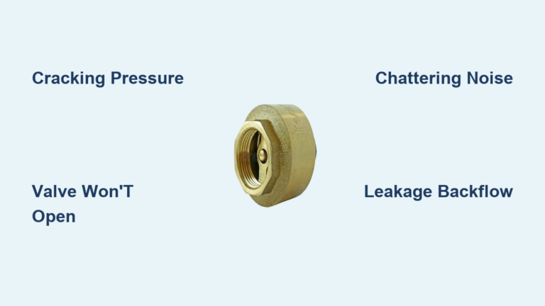
The valve opens and closes based on pressure differential. When pressure at the inlet exceeds the cracking pressure (typically 3 to 7 psi), the internal sealing element lifts off its seat, allowing flow. Once inlet pressure drops or reverse pressure is applied, the valve closes instantly.
No electricity or manual input is needed. Like a diode in an electrical circuit, it enforces flow direction using only system dynamics. If pressures equalize on both sides, the internal spring keeps the valve sealed, preventing leakage even under high static pressure.
Internal Components and Movement
Key parts include:
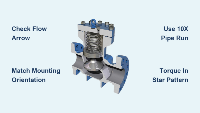
- Sealing element: Ball, poppet, disc, or flapper
- Valve seat: Precision-machined surface for sealing
- Spring: Ensures rapid closure and defines cracking pressure
- Body: Houses all components with defined inlet and outlet ports
When forward pressure overcomes spring force, the sealing element moves, creating a flow path. Reverse pressure pushes it tighter against the seat, enhancing the seal.
Common Check Valve Types
Different designs suit different flow, pressure, and response needs. Choosing the right type ensures efficiency and longevity.
Ball Check Valves
A small ball made of steel or ceramic seals against a conical seat.
How it works: Inlet pressure lifts the ball, allowing flow around it. Reverse pressure forces the ball into the seat, blocking flow.
Pros:
- Simple, durable design
- Effective in high-cycle applications
- Resistant to wear
Cons:
- Point contact seal can leak if debris scratches the seat
- May not seal perfectly in horizontal installations without spring assist
Best for: General-purpose pneumatic lines, compressors, and low-debris systems.
Poppet Check Valves
Uses a plunger-like poppet with a resilient seal such as an O-ring or flat face.
How it works: Inlet pressure lifts the poppet, and reverse pressure drives it into the seat. Many use balanced poppet designs where system pressure assists in lifting, reducing spring load and wear.
Balanced vs. Standard:
- Standard: Spring bears full load, limited to lower pressures
- Balanced: Pressure acts on poppet areas to reduce seal stress, handles up to 3000 PSI in some models
Best for: High-pressure systems, precision control circuits, and applications requiring minimal leakage.
Inline and Flow Direction Types
Valves are designed for specific installation methods and flow paths.
Inline Check Valves
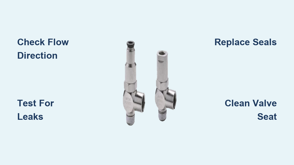
Compact, threaded or push-in valves installed directly in air lines.
Features:
- Minimal pressure drop
- Direct replacement in pipelines
- Available in brass, stainless steel, and plastic
Use when: You need simple, permanent unidirectional flow control in standard pneumatic tubing.
Flow-to-Thread vs. Flow-from-Thread
Defined by connection type and direction:
| Type | Flow Direction | Use Case |
|---|---|---|
| Flow to Thread | Push-in (hose) to Threaded port | Deliver air from flexible hose to fixed equipment |
| Flow from Thread | Threaded port to Push-in (hose) | Send air from fixed line to portable tool |
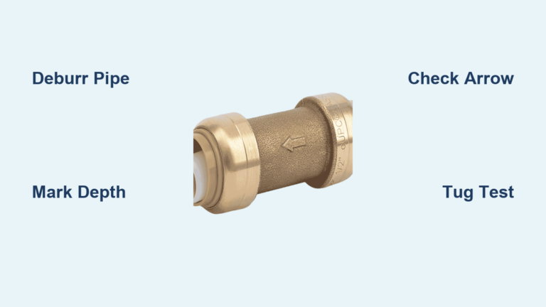
Why it matters: Using the wrong type blocks flow. Always match the arrow on the valve body to your system’s intended direction.
Auto Shut-off Fittings
Specialized quick-connects with integrated check valves.
Function: Automatically seal when a hose is disconnected, preventing system-wide depressurization.
Benefits:
- Saves energy
- Reduces compressor cycling
- Improves safety during tool changes
Common in: Workshop air systems and production lines with frequent tool swaps.
Pilot-Operated Check Valves
Unlike standard check valves, pilot-operated models require an external signal to open in reverse, making them ideal for safety and load-holding applications.
How Pilot Operation Works
A pilot-operated check valve (POCV) blocks reverse flow even under high outlet pressure. To release trapped air from a cylinder, a pilot signal (air pressure) is applied.
Internal mechanism:
- Main poppet is held shut by system pressure and spring
- Pilot pressure acts on a secondary piston
- This forces the poppet open, allowing reverse flow
Key advantage: A small pilot signal can unlock large trapped pressures, which is critical in automation and safety systems.
Pilot Pressure Ratio
Efficiency is measured by the pilot-to-trapped pressure ratio.
- Example: A 4:1 ratio means 20 psi pilot pressure can release 80 psi of trapped air
- High-efficiency models: Ratios as low as 3:1 available
- Adjustable versions: Allow tuning for faster actuator stopping or partial exhaust control
Design tip: Ensure your control system provides sufficient pilot pressure to overcome the trapped load.
Integrated Features and Options
Modern POCVs offer advanced functionality:
- Manual release button: Safely vent trapped air during maintenance
- Built-in flow control: Regulate exhaust speed for smooth cylinder retraction
- Swivel mounts: Simplify installation in tight spaces
- Single-side ports: Ideal for compact manifolds
Materials:
- 316 Stainless Steel: For corrosive, washdown, or outdoor use
- High-temp seals (-V): Operate up to 300°F
- Low-temp seals (-T40): Function down to -40°F
Flow capacity (Cv): Ranges from 0.5 Cv (small tube) to 3.8 Cv (½” to ¾” NPT), supporting high-demand actuators.
Key Applications in Pneumatic Systems

Check valves are not just accessories; they enable core system functions across industries.
Air Compressor Tank Protection
Installed at the compressor outlet, the check valve prevents tank air from flowing back into the pump.
Why it is critical:
- Stops reverse pump rotation when motor shuts off
- Prevents load starting (motor starts against zero pressure)
- Maintains system pressure for next startup
Failure sign: Compressor struggles to start or makes a grinding noise, indicating back-pressure from the tank.
Pressure and Vacuum Maintenance
Check valves lock in pressure or vacuum until needed.
In receiver tanks:
- Keeps compressed air stored
- Reduces compressor cycling
- Saves energy
In vacuum systems:
- Prevents atmospheric air from breaking vacuum
- Ensures suction cups hold securely
- Maintains efficiency in pick-and-place robots
Real-world impact: A failed vacuum check valve causes dropped parts and production delays.
Pneumatic Tool Efficiency
Tools like impact wrenches and nail guns use internal check valves.
Functions:
- Maintain internal pressure during idle
- Prevent backflow into supply line
- Ensure instant power delivery
Benefit: Longer tool life, consistent performance, and reduced air waste.
Quick-Connect Fittings with Check Valves
Auto-shut-off couplers use built-in check valves.
How it works:
- Coupler seals when hose is disconnected
- Main line stays pressurized
- Tool change does not waste air
Result: Up to 30% less compressor runtime in high-usage environments.
Circuit Logic and Control Functions
Check valves do more than block flow; they enable smart pneumatic logic.
Bypass Flow Control Circuits
Used with speed controllers to allow free flow in one direction.
Setup:
- Check valve in parallel with a flow control valve
- Free flow: Air bypasses restriction
- Restricted flow: Air forced through metering orifice
Application: Cylinder speed control, such as fast retract and slow extend.
Visual cue: Schematic shows check valve parallel to a throttle symbol with arrow.
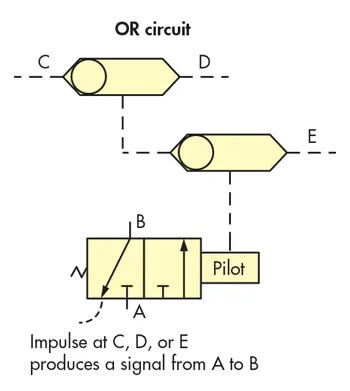
Shuttle Valve Logic (OR Function)
Two check valves combine to select the higher of two pressures.
How it works:
- Each input has its own check valve
- Whichever side has higher pressure opens its valve
- Output receives the dominant signal
Use cases:
- Dual-compressor systems
- Manual override circuits
- Safety interlocks
Logic equivalent: Pneumatic “OR” gate.
Sequential Operation Control
Ensures stages activate only when pressure is available.
Example: Stage 2 of a process only runs if Stage 1 has built sufficient pressure, preventing premature actuation.
Design tip: Install check valve before pressure switch to maintain sensing pressure.
Multi-Source Isolation
Prevents air from one compressor flowing into another.
Problem without check valves:
- Running compressor feeds idle unit
- Causes overheating, wear, or backflow
Solution: Install check valve on each compressor output.
Selection Criteria for Optimal Performance
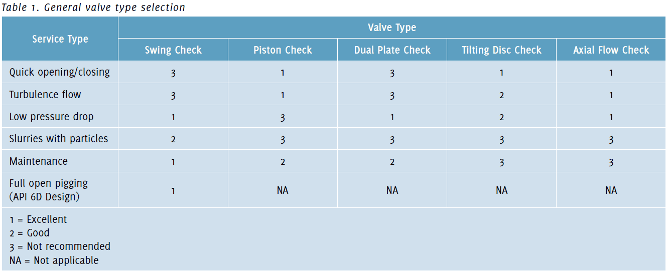
Choosing the wrong valve leads to failure. Match specs to your system demands.
Connection Types
| Type | Pros | Cons | Best For |
|---|---|---|---|
| Threaded (NPT, BSP) | Vibration-resistant, leak-tight | Permanent, harder to change | Fixed installations |
| Push-in (Quick-connect) | Tool-free, fast assembly | Less durable under vibration | Maintenance-heavy systems |
Installation tip: Never over-tighten threaded valves, as this can crack the body or distort the seat.
Cracking Pressure
Minimum pressure to open the valve.
- Standard: ~5 psi (0.35 bar)
- Low/Zero Cracking: Less than 1 psi, used in sensitive instruments
- High Sensitivity: Needed for low-pressure logic circuits
Warning: Too high a cracking pressure delays system response.
Flow Capacity (Cv)
Determines how much air passes through.
- Undersized valve = pressure drop, heat, poor performance
- Cv range: 0.5 (small tube) to 3.8 (large NPT)
- Rule of thumb: Match Cv to actuator demand
Check: Use manufacturer flow charts to verify performance at your operating pressure.
Material and Seal Compatibility
Match materials to environment.
| Body Material | Use Case |
|---|---|
| Brass | General-purpose, dry air |
| 316 Stainless Steel | Corrosive, washdown, outdoor |
| Plastic/Nylon | Lightweight, non-sparking |
| Seal Type | Temp Range | Use Case |
|---|---|---|
| Nitrile (Buna-N) | -40°F to 212°F | Standard air |
| Viton | -40°F to 300°F | High heat, oils |
| Low-temp compound | -40°F to 150°F | Freezers, cold environments |
Pro tip: Upgrade to stainless steel if rust is recurring. Do not just replace failed brass valves.
Troubleshooting Check Valve Failures
Most failures show clear symptoms. Diagnose early to avoid downtime.
Common Failure Signs
- Air leakage from compressor unloader
- Pressure drops overnight
- Compressor short-cycles
- Motor struggles to start
- Hissing or rattling noises
Immediate action: Isolate and test the check valve.
Root Causes and Fixes
-
Debris in Seat
– Cause: Dirt, rust, pipe scale
– Fix: Install upstream filter (FRL unit)
– Prevention: Use air line filters and drain tanks daily -
Worn or Hardened Seals
– Cause: Age, heat, poor air quality
– Fix: Replace O-rings or entire valve
– Tip: Use Viton seals in hot environments -
Spring Failure
– Cause: Fatigue, overpressure
– Fix: Replace spring or valve
– Check: Ensure system pressure is below valve rating -
Corrosion on Ball or Seat
– Cause: Moist air, no dryer
– Fix: Replace with stainless steel model
– Solution: Add air dryer or coalescing filter -
Improper Installation
– Cause: Installed backward or over-tightened
– Fix: Reinstall with arrow facing flow direction
– Warning: Backward installation blocks all flow
Diagnostic Testing Methods
Verify valve function with simple tests.
Reverse Flow Test
- Blow air into the outlet
- If air passes through, the valve fails
- No airflow means a good seal
Tool: Use a hand pump or regulated air source.
Soapy Water Leak Test
- Pressurize the outlet side
- Apply soapy water to inlet and body
- Bubbles indicate leak location
Best for: Finding small leaks in seated condition.
Pressure Decay Test
- Isolate valve with trapped pressure
- Monitor gauge over 10 to 30 minutes
- Any drop indicates internal leakage
Use case: Verifying pilot-operated valve seal integrity.
Visual Inspection
Check for:
- Cracked body
- Corroded threads
- Damaged O-rings
- Misaligned flow arrow
Pro move: Disassemble (if serviceable) to inspect seat surface.
Maintenance Best Practices
Prevent failure before it happens.
Install Upstream Filtration
Use an FRL (Filter-Regulator-Lubricator) unit before every check valve.
- Filter: Removes particles larger than 5 microns
- Regulator: Prevents overpressure
- Lubricator: Extends seal life (if needed)
Result: 3x longer valve life in dirty systems.
Schedule Seal Replacement
Even in clean systems, seals degrade.
- Replace every 2 to 3 years in continuous use
- Check during annual maintenance
- Keep spares on hand
Upgrade Materials Proactively
If failures repeat:
- Switch to stainless steel in wet environments
- Use Viton seals above 200°F
- Install air dryers to reduce moisture
Avoid Over-Tightening
Hand-tight plus 1/4 turn is usually enough for NPT threads.
Damage risk:
- Cracked valve body
- Distorted seat
- Leaks that worsen with pressure
Schematic Symbols and Identification
Reading pneumatic diagrams helps locate and diagnose valves.
Standard Check Valve Symbol
- ISO 1219-1: Circle with arrow showing free flow direction
- Arrow on body: Must match system flow
Tip: If arrow points the wrong way, the valve blocks flow.
Pilot-Operated Symbol
- Same base symbol
- Dashed line to pilot port
- Indicates external signal required to open
On schematic: Look for control line from solenoid or pilot valve.
Flow Control with Bypass
- Check valve in parallel with throttle symbol
- Allows free flow one way, restricted the other
Common in: Double-acting cylinder circuits.
Standard vs. Pilot-Operated: When to Use Which
| Feature |