A single misaligned arrow can shut down your entire system. Many technicians discover too late that an improperly installed piston check valve causes chatter, leaks, or water hammer that damages upstream equipment. Getting piston check valve installation right protects your piping, prevents costly downtime, and ensures the valve performs as designed for years.
This guide walks you through every critical phase of installation, from pre-installation safety checks to startup verification. You will learn how to verify flow direction, choose the correct mounting orientation, avoid common sizing mistakes, and confirm reliable operation after startup.
Verify Flow Direction and Valve Alignment
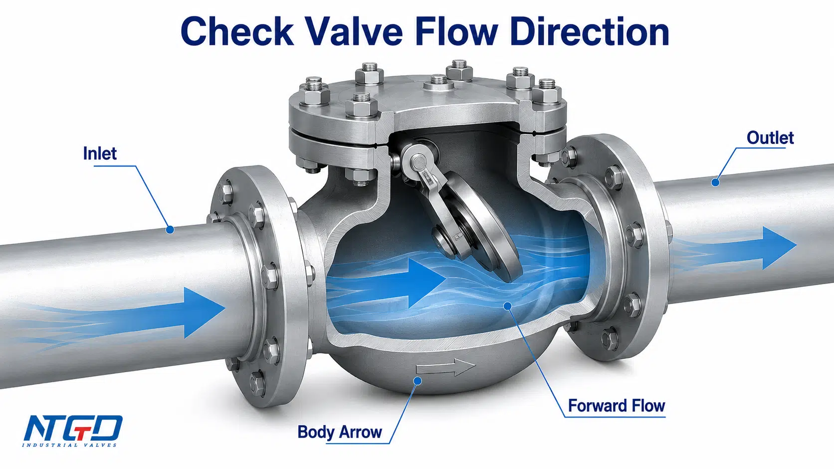
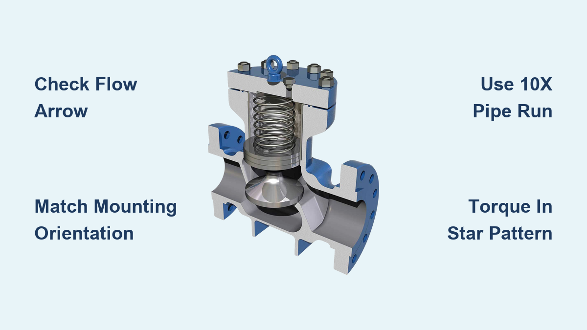
Every piston check valve has a cast or stamped arrow on the body that marks the required direction of flow. Installing the valve backward blocks forward flow completely and may damage the piston or connected equipment. Before removing protective end caps, confirm the arrow points in the direction of fluid travel.
Match Arrow to System Flow
The flow arrow must align exactly with your piping system’s intended fluid path. A backward installation creates immediate operational failure and potential damage.
Before final placement, verify:
– The arrow points in the correct flow direction
– Your system’s flow path is clearly marked or documented
– No conflicting fittings could reverse flow unintentionally
Pro Tip: Photograph the valve with the arrow visible before installation. This reference helps during future maintenance or system audits.
Prevent Cross-Connection Errors
Complex systems with multiple branch lines increase the risk of misrouting. Double-check your piping schematics or isometric drawings before installation. Confirm the location of upstream and downstream components such as pump discharge points.
If the arrow is missing, faded, or unclear, do not install the valve. Contact the manufacturer for model verification instead.
Choose Correct Mounting Orientation
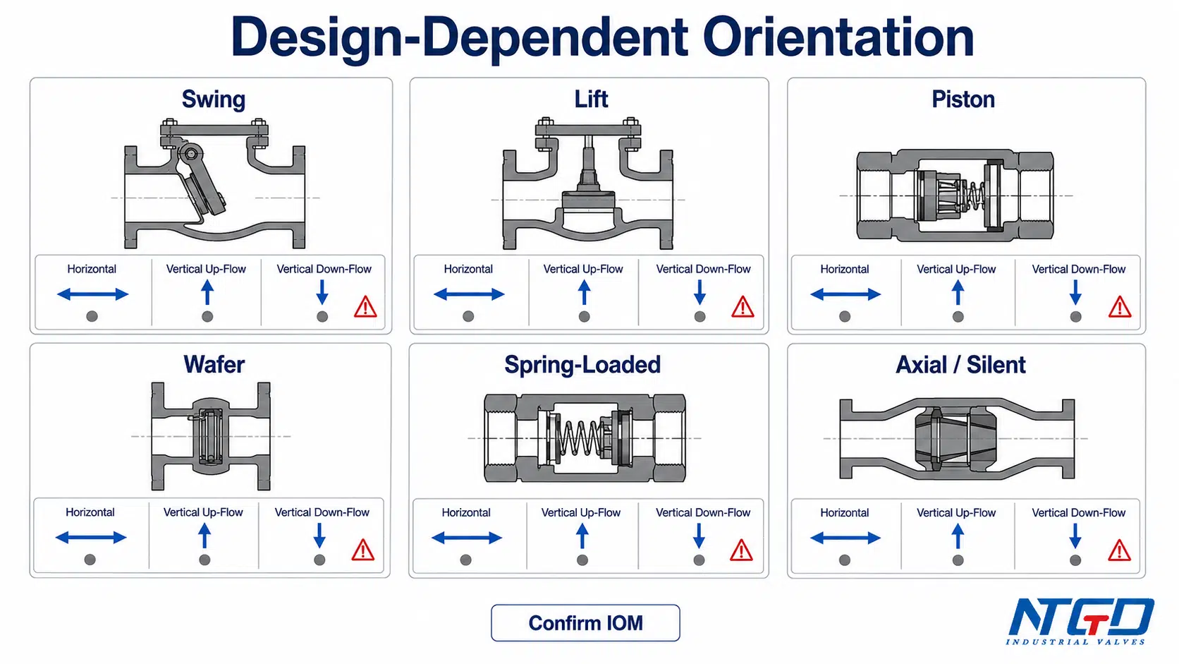
Mounting orientation directly affects how the piston seats and closes. The wrong orientation can cause the piston to float open or stick, leading to backflow and system contamination.
Install Horizontally When Possible
Most piston check valves perform best in horizontal piping. This orientation allows gravity and spring force to work together, ensuring smooth piston return and consistent seating. Horizontal mounting also minimizes stress on internal guides and reduces debris accumulation.
Ensure the valve sits level and is supported by pipe hangers. Check that no sagging or misalignment exists in adjacent piping.
Vertical Installation: Upflow vs. Downflow
Piston check valves can be installed vertically, but only if the design supports it.
Flow Upward (Recommended):
– Common in risers or vertical discharge lines
– Gravity assists closure when flow stops
– Use a spring-loaded model to ensure full seating under low-pressure conditions
Flow Downward (Use Caution):
– Only possible with heavy-duty spring-assisted valves
– Gravity pulls the piston open, so the spring must overcome fluid static head and piston weight
– Consult manufacturer specifications, since many standard models are not rated for downward vertical flow
Warning: Installing a non-rated valve in vertical downflow can cause the piston to float open, leading to backflow and system contamination.
Angled Installations (30° to 45°)
Some universal spring-loaded piston check valves allow installation at angles up to 45° from horizontal or vertical. These models work well in tight spaces or sloped piping runs.
Requirements for angled installation:
– Confirm the valve is rated for angled use by checking the datasheet
– Ensure adequate upstream straight run of 10 pipe diameters
– Support both pipe and valve to prevent torque on flanges
Prepare System for Safe Installation
Safety comes first when working with pressurized systems. Skipping preparation steps risks injury, equipment damage, and contamination.
Shut Down and Depressurize Line
Before handling the valve, shut off the pump or system supply. Close isolation valves upstream and downstream of the installation point. Bleed pressure using vent valves or drain ports.
Confirm zero pressure on gauges on both sides of the valve.
Critical Step: Implement Lockout/Tagout (LOTO) procedures to prevent accidental startup during installation.
Drain and Flush Piping
Remove all fluid from the section where the valve will be installed. Then open upstream piping and flush thoroughly. Use clean water or air to remove scale, welding slag, dirt, and debris.
Inspect flushed water for particulates and repeat until the discharge runs clean.
Why It Matters: Debris is a leading cause of piston sticking, seat damage, and premature valve failure.
Handle Hazardous Media Safely
If the line previously carried corrosive, toxic, or flammable fluids, take extra precautions. Review the Safety Data Sheet (SDS) for exposure risks before beginning work.
Wear full PPE including gloves, goggles, face shield, apron, and respirator if needed. Have emergency rinse stations and fire extinguishers nearby. Decontaminate the area before and after installation work.
Inspect Valve and Select Gaskets
A damaged valve or wrong gasket choice can undermine even a perfect installation. Take time to inspect components and match materials to your system.
Check for Damage and Compatibility
Inspect the new valve for shipping cracks, dents, or missing end protectors. Verify that the model number matches your specification sheet. Confirm correct size, material (brass, stainless steel), and pressure rating such as ANSI Class 300.
Check temperature and media compatibility. For example, NBR diaphragms work well for oil, while PTFE suits chemical applications. Leave protective caps on until just before installation to keep out dust and moisture.
Choose the Right Gasket or Sealant
For Flanged Connections:
– Use gaskets rated for system pressure and temperature
– Common types include spiral wound, rubber, graphite, and metal-jacketed
– Ensure the inner diameter does not protrude into the flow path
For Threaded Ends:
– Apply PTFE tape or pipe dope sparingly
– Wrap tape clockwise (viewed from the end) for 3 to 5 turns
– Avoid excess material that can break off and jam the piston
Never use sealant inside the valve body.
Mount and Secure the Valve
Proper mounting prevents leaks, misalignment, and premature wear. Follow a systematic approach to ensure even compression and correct alignment.
Align Valve and Piping
Before bolting, align flanges perfectly with no forced fits. Use alignment pins if necessary to center the valve. Ensure the valve runs parallel to the pipe axis.
Misalignment creates stress concentrations that cause leaks and shorten valve life.
Torque Bolts in Star Pattern
For flanged valves, follow this sequence:
1. Insert bolts hand-tight
2. Tighten in a cross-pattern or star sequence to compress the gasket evenly
3. Use a calibrated torque wrench set to manufacturer specifications
Torque Tips:
– Under-tightening causes leaks
– Over-tightening distorts the body, cracks flanges, or crushes gaskets
Refer to the valve manual for exact torque values by size and pressure class.
Support the Piping
Install pipe hangers or supports within 2 to 3 feet of the valve. Never let the valve bear the weight of the pipe.
Unsupported weight leads to flange leaks, misalignment, and cracked valve bodies.
Follow Upstream Piping Rules
The piping configuration upstream of the valve directly affects performance. Turbulent flow causes chatter, noise, and premature wear.
Maintain 10 Pipe Diameters of Straight Run
Install the valve at least 10 pipe diameters downstream of pumps, elbows, tees, or control valves. For a 2-inch pipe, allow 20 inches (1.67 feet) of straight pipe before the check valve.
Smooth, laminar flow ensures stable operation. Turbulent flow from bends or pumps causes piston chatter, which leads to noise, erosion, and spring fatigue.
Avoid Installing After Control Valves
Placing a check valve immediately downstream of a modulating control valve exposes it to pulsating flow and cavitation. Add sufficient straight run or a damping section to reduce these effects.
For pulsating systems, consider a pulsation-resistant model such as Series 7100 designs with integrated damping orifices.
Test After Installation
Post-installation testing confirms that the valve works correctly under real operating conditions. Skipping this step risks discovering problems only after full system startup.
Perform Visual and Leak Check
After mounting, confirm the flow arrow still points correctly. Inspect all joints for gaps or misalignment. Ensure bolts are torqued and the valve is properly supported.
Pressurize Gradually
Slowly open the upstream isolation valve. Watch for leaks at flanges or threads. Listen for unusual noises such as hissing or chattering. Check the valve body for stress or bulging.
If leaks occur, depressurize immediately. Re-torque bolts in a star pattern. Replace the gasket if damaged.
Observe Opening and Closing
Run the system at normal operating conditions. Confirm the piston lifts smoothly and you hear steady flow. Stop the flow and verify the valve closes promptly and quietly.
Signs of Trouble:
– Chatter: Rapid clicking or buzzing indicates the valve may be oversized or upstream turbulence exists
– Slamming: A loud bang suggests the spring is too weak or orientation is wrong
– Delayed closure: Possible debris or a worn spring
Size the Valve Correctly to Prevent Chatter
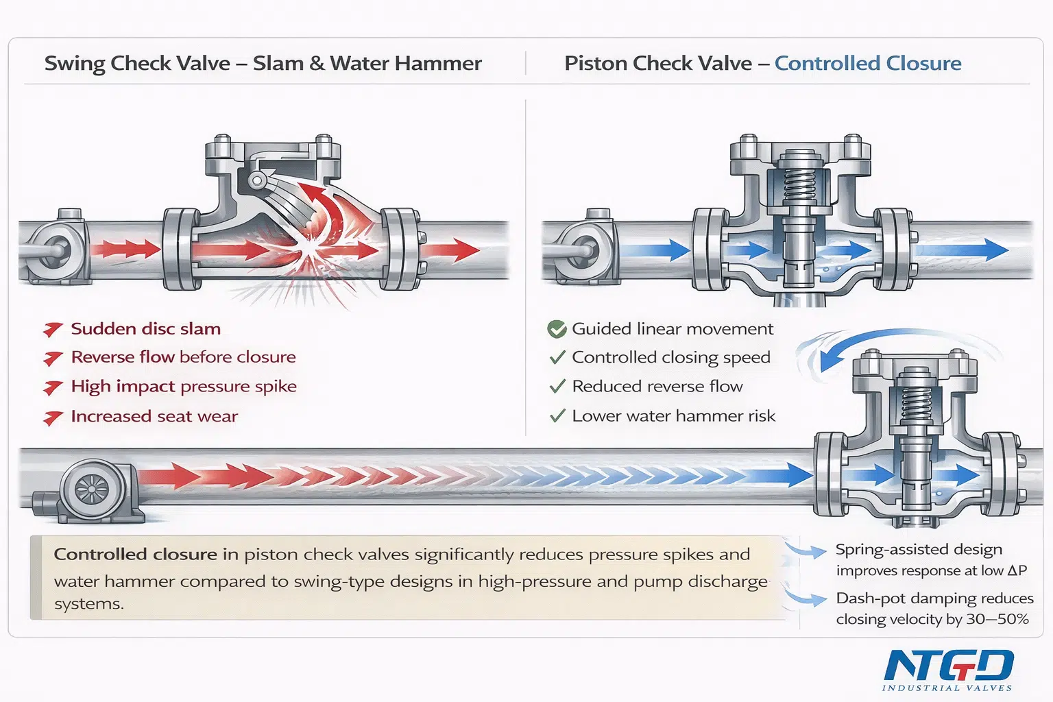
Sizing affects more than pipe diameter. A valve must fully open under actual operating conditions to avoid partial-opening problems.
Match Flow Rate and Pressure
The valve should operate in only two states: fully open or fully closed. Partial opening causes rapid oscillation and damage.
Problem: Oversizing
– Low flow rates fail to lift the piston fully
– The piston hovers near the seat, causing chatter, seat erosion, and eventual failure
Example: A 1-inch valve in a line with 300 PSI but only 0.005 GPM may not open due to insufficient flow volume, even with high pressure.
Solution: Select a smaller valve or one with a low cracking pressure spring.
Calculate Cracking Pressure Needs
Cracking pressure is the minimum pressure required to lift the piston off its seat. Choose based on system pressure, flow rate, and installation orientation.
Use cases include:
– Low cracking pressure: For low-pressure systems or vertical risers
– High cracking pressure: To prevent leakage in downflow or dampen water hammer
Consult manufacturer charts to match the flow coefficient (Cv) with your system’s requirements.
Maintain and Troubleshoot
Routine maintenance extends valve life and prevents unexpected failures. Listen, inspect, and clean on a regular schedule.
Listen for Abnormal Noises
Routine checks should include listening for:
– Chatter: Indicates partial opening. Check sizing or upstream flow conditions.
– Humming: May signal piston vibration. Inspect for debris.
– Silence on closure: A good sign that the spring is working correctly.
Clean Internally If Performance Drops
If backflow occurs or flow resistance increases, follow these steps:
1. Isolate and depressurize the valve
2. Remove it from the line
3. Disassemble if repairable
4. Inspect the seat and piston for scoring, the spring for corrosion or fatigue, and the guide for blockage
Clean with a solvent compatible with internal materials, such as isopropyl alcohol for NBR seals.
Replace Rather Than Repair When Needed
Many piston check valves are non-repairable. If the seat is damaged, the spring is weak, or the piston is scored, replace the entire valve.
Pro Tip: Keep spare valves on hand for critical systems to minimize downtime.
Store Unused Valves Properly
Proper storage preserves valve integrity until installation. Poor storage conditions lead to contamination and damage.
Before installation, store valves in a dry, climate-controlled environment. Keep end caps installed at all times. Avoid exposure to dust, moisture, or chemicals.
For long-term storage:
– Inspect every 6 months
– Reapply light lubricant if specified, such as silicone-based products
– Never store valves in direct sunlight or freezing conditions
Frequently Asked Questions About Piston Check Valve Installation
What is the correct flow direction for a piston check valve?
The flow direction is marked by a cast or stamped arrow on the valve body. This arrow must point in the direction of fluid flow. Installing the valve backward blocks flow completely and may damage the piston or upstream equipment.
Can a piston check valve be installed vertically?
Yes, but only if the valve is designed for vertical installation. Spring-loaded universal models can be installed vertically with flow going up or down. Standard gravity-assisted designs should only be installed horizontally or vertically with upward flow.
How far upstream should a check valve be from a pump?
Install the check valve at least 10 pipe diameters downstream of pumps, elbows, tees, or control valves. This distance ensures smooth, non-turbulent flow into the valve and prevents chatter and premature wear.
What causes a piston check valve to chatter?
Chatter typically results from an oversized valve, insufficient flow rate, excessive upstream turbulence, or wrong spring stiffness. The piston hovers near the seat and oscillates rapidly, causing noise and seat erosion.
How tight should flange bolts be on a check valve?
Tighten flange bolts in a star pattern using a calibrated torque wrench set to the manufacturer’s specifications. Under-tightening causes leaks, while over-tightening can distort the body or crush the gasket.
When should a piston check valve be replaced instead of repaired?
Replace the valve when the seat is damaged beyond acceptable leakage limits, the spring is fatigued or corroded, or the piston shows scoring. Many modern piston check valves are non-repairable and designed for full replacement.
Key Takeaways for Successful Piston Check Valve Installation
Proper piston check valve installation ensures reliable backflow prevention, reduces water hammer, and extends system life. Always verify flow direction by checking the arrow on the valve body. Install in the correct orientation, with horizontal preferred and vertical only when using spring-loaded designs rated for that position.
Maintain at least 10 pipe diameters of straight upstream piping to prevent turbulence. Torque flanges correctly using a star pattern and a calibrated wrench. Size the valve for actual flow conditions, not just pipe diameter, to avoid chatter and premature failure.
For specific models, always consult the manufacturer’s datasheet, especially for vertical or angled installations. When in doubt, choose a spring-loaded universal design for maximum flexibility and performance. Keep spare valves on hand for critical systems to minimize downtime when replacement becomes necessary.