Installing a spring check valve correctly protects pumps, prevents backflow, and keeps your system running efficiently. Whether you work on residential plumbing, industrial lines, or pool circulation setups, a poor installation can cause leaks, water hammer, or total flow blockage. This guide walks you through every critical step of spring check valve installation, from pre-installation checks to final testing.
You will learn how to confirm flow direction, prepare pipes, secure connections without damaging the valve, and avoid the most common installation mistakes. By the end, your system will operate quietly and reliably with no callbacks or premature failures.
Verify Flow Direction Before Installation
Match the Arrow to System Flow
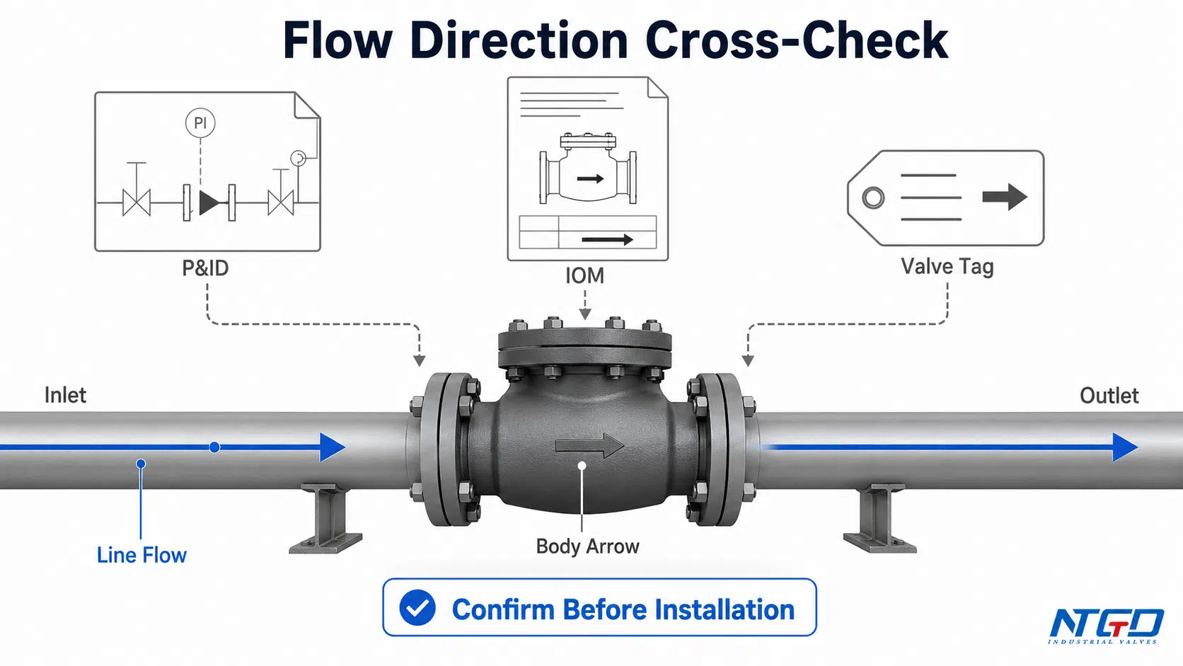
The number one error during spring check valve installation is mounting the valve backward. These valves are strictly directional. Fluid must enter the inlet side to push the disc open against the spring. A reversed valve stays shut and blocks all flow.
Before picking up any tools, take these steps:
– Locate the directional arrow stamped or embossed on the valve body.
– Trace your pipe run and identify the intended flow direction.
– Confirm the arrow points with the flow, not against it.
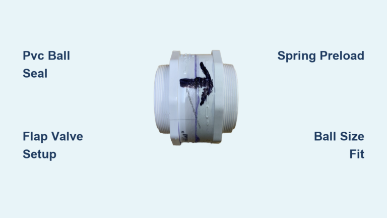
✅ Pro Tip: Mark the arrow with a permanent marker once aligned. This speeds up future maintenance or reassembly work.
Choose the Right Installation Orientation
Flexible Positioning for Any System
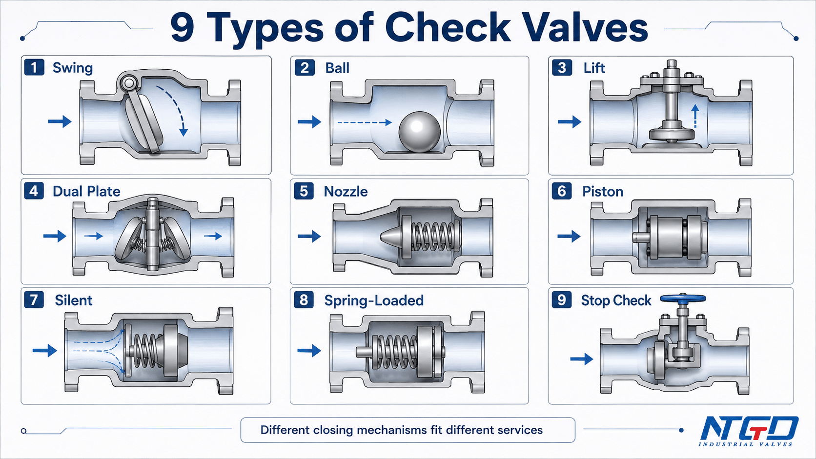
Unlike swing check valves that rely on gravity, spring check valves use mechanical spring force to close the disc. This design allows full orientation flexibility:
– Horizontal pipe runs
– Vertical pipes with upward flow
– Vertical pipes with downward flow
– Inverted or upside-down mounting
However, orientation still affects performance. Vertical downward flow requires a spring strong enough to overcome the weight of the fluid column above the disc. Pump discharge lines should use vertical upward or horizontal mounting to prevent backflow when the pump shuts off.
⚠️ Avoid: Installing near sharp elbows or tees. Turbulent flow causes disc flutter, which creates noise and accelerates wear.
Maintain Proper Pipe Spacing
Prevent Turbulence and Premature Wear
Smooth, laminar flow extends valve life and ensures stable operation. Install the valve on a straight section of pipe with these minimum distances:
– Upstream: 5 pipe diameters of straight pipe
– Downstream: 10 to 15 pipe diameters of straight pipe
For example, a 1-inch pipe needs 5 inches of straight run before the valve and 10 to 15 inches after. A 2-inch pipe needs 10 inches before and 20 to 30 inches after. These spacing rules reduce turbulence, balance pressure distribution, and prevent erratic disc movement.
❌ Failure Risk: Short straight runs cause disc chatter, leading to noise, erosion, and eventual valve failure.
Prepare Pipes and the Valve
Cleanliness Prevents Leaks
Debris trapped between the disc and seat is the leading cause of spring check valve failure. Particles prevent a tight seal and cause backflow or leakage.
Follow these preparation steps:
1. Flush the line thoroughly before installation, especially after cutting or welding.
2. Inspect pipe ends and remove burrs, slag, or thread shavings with a deburring tool.
3. Check the valve interior by shaking gently to listen for loose debris.
4. Press the disc if accessible to verify smooth spring movement.
✅ Best Practice: Cap open pipe ends during assembly to keep contamination out.
Install Based on Connection Type
Threaded Connections (NPT or BSPT)
- Apply PTFE tape or thread sealant to the male threads only.
- Hand-tighten the valve into position while aligning the flow arrow.
- Use a wrench on the valve’s hex end, never the body, to prevent cracking.
- Tighten 1 to 2 turns past hand-tight without forcing.
⚠️ Warning: Over-tightening brass valves warps the seat and causes leaks.
Flanged Connections
- Align the flanges and insert the correct gasket material.
- Insert bolts and hand-tighten all nuts.
- Torque bolts in a star pattern to manufacturer specifications.
- Re-torque after the first pressurization cycle if required.
✅ Pro Tip: Use stainless steel bolts in outdoor or wet environments to prevent galvanic corrosion.
Compression Ring Connections
- Slide the nut and ferrule onto the pipe.
- Insert the pipe into the valve until it reaches the internal stop.
- Tighten the nut by hand, then secure with a quarter to half turn using a wrench.
- Avoid over-tightening, which deforms the ferrule and weakens grip.
❌ Common Mistake: Reusing old ferrules. Always install new ones for a reliable seal.
Solvent Weld (Glued Sleeve) Connections
- Clean the pipe and socket with primer or solvent.
- Apply compatible cement designed for the pipe material.
- Insert the pipe with a quarter turn to spread adhesive evenly.
- Hold for 30 seconds and allow full cure time before pressurizing.
⚠️ Critical: Use only approved solvents. Wrong chemicals weaken the joint.
Push-In Fittings
- Cut the pipe square and deburr the edge.
- Push the pipe straight into the fitting until it clicks and seats fully.
- Pull back gently to confirm the locking mechanism engaged.
- Engage any external clips required by the system design.
✅ Advantage: No tools needed, making these ideal for tight spaces.
Hose Barb with Clamp
- Slide the hose clamp onto the hose before attachment.
- Push the hose fully onto the barb with no gaps.
- Position the clamp over the barb ridge and tighten securely.
❌ Avoid: Using a single clamp on long hoses. Use two clamps for high-pressure lines.
Victaulic (Grooved) Connections
- Confirm pipe ends are properly grooved to specification.
- Slide the gasket over the pipe and align with the valve hub.
- Position the coupling housing and insert bolts.
- Tighten bolts evenly until the gasket compresses fully.
✅ Use Case: Ideal for large-diameter industrial lines where flanges are impractical.
Union Connections for Pool and Irrigation Systems
- Unscrew the union collars from the existing line.
- Inspect O-rings and replace any that are cracked or swollen.
- Lubricate O-rings with silicone grease only.
- Insert the valve with the arrow aligned and hand-tighten the collars.
- Tighten slightly more if a minor drip occurs, but never force the connection.
✅ Why Unions Matter: They allow tool-free removal for cleaning or replacement, which is critical in pool systems prone to debris buildup.
Apply Correct Torque and Alignment
Avoid Stress and Body Warping
Misaligned pipes or over-tightened connections transfer stress to the valve body. This leads to cracks or seat distortion over time.
Follow these best practices:
– Never force alignment. Use adjustable couplings or re-cut pipes instead.
– Support heavy piping near the valve to prevent sagging.
– Use torque wrenches on flanged and compression fittings.
– Tighten gradually and evenly across all multi-bolt connections.
❌ Red Flag: A crooked valve or twisted union indicates stress. Correct it before pressurizing.
Test the System After Installation
Confirm Function and Seal Integrity
Never assume the valve works without testing. Run through these verification steps:
1. Close downstream valves if applicable.
2. Open the supply slowly to prevent water hammer.
3. Check all joints for leaks and tighten slightly if dripping occurs.
4. Open the downstream valve and confirm water flows freely.
5. Test backflow prevention by shutting off supply and opening a downstream drain.
6. Listen for rattling or banging, which signals disc flutter or turbulence.
✅ Pro Tip: Add food coloring upstream during shutdown to visually confirm zero backflow.
Prevent Common Installation Failures
Fix Issues Before They Cause Downtime
| Problem | Cause | Solution |
|---|---|---|
| Leaking seat | Debris, worn soft seat, over-tightened body | Flush line and replace valve |
| No flow | Valve installed backward | Rotate valve to match flow arrow |
| Water hammer | Rapid closure or wrong cracking pressure | Use lower cracking pressure or add surge tank |
| Disc chatter | Turbulent flow or short straight run | Ensure 5D upstream and 15D downstream |
| O-ring leaks | Dry, cracked, or misaligned O-rings | Replace and lubricate with silicone grease |
✅ Maintenance Tip: Install a basket strainer upstream in dirty systems like irrigation lines to catch debris before it reaches the valve.
Select the Right Seat and Body Material

Match the Valve to Your Application
Soft Seats (Viton or PTFE)
– Best for clean water, chemicals, and tight shutoff
– Provide near-zero leakage
– Degrade quickly with sand, grit, or high heat
Metal Seats (Stainless Steel)
– Best for steam, abrasive slurries, and high temperatures up to 537°C
– Handle harsh conditions and hydraulic shock
– May leak slightly at low pressure
Body Materials
– Brass pairs well with copper plumbing and avoids galvanic risk
– Stainless Steel (SS316) resists corrosion and requires a plastic isolator when connecting to copper
❌ Never direct-connect stainless steel to copper. Use a dielectric union or plastic coupling to prevent galvanic corrosion.
Compare Spring and Swing Check Valves

Choose the Right Type for Your System
| Feature | Spring Check Valve | Swing Check Valve |
|---|---|---|
| Orientation | Any position | Horizontal only |
| Closing Speed | Fast spring actuation | Slow flow-dependent closure |
| Backflow Seal | Tight even at low pressure | May leak at low reverse pressure |
| Water Hammer Risk | Low when sized correctly | High due to slam closure |
| Ideal Use | Pumps, vertical lines, high pressure | Large horizontal pipes with low velocity |
✅ Choose spring check valves when you need orientation flexibility, reliable backflow protection, or dynamic system performance.
Final Installation Checklist
Confirm these items before pressurizing the system:
– Flow arrow matches system direction
– 5D straight pipe upstream and 10 to 15D downstream
– Pipes flushed and deburred
– Correct connection method used and properly tightened
– No stress or misalignment on the valve body
– O-rings lubricated and seated correctly
– System tested for flow, leaks, and backflow prevention
Frequently Asked Questions About Spring Check Valve Installation
What is the cracking pressure for a spring check valve?
Cracking pressure is the minimum upstream pressure needed to push the disc open against the spring. Standard values are 0.5, 1.0, or 2.0 bars, though manufacturers can customize these settings for specific applications.
Can a spring check valve be installed vertically?
Yes. Spring check valves work in any orientation, including vertical upward flow, vertical downward flow, horizontal runs, and inverted positions. Vertical downward flow requires a spring strong enough to overcome the weight of the fluid column above the disc.
How much straight pipe is needed before and after the valve?
Install a minimum of 5 pipe diameters of straight pipe upstream and 10 to 15 pipe diameters downstream. This spacing prevents turbulence, disc chatter, and premature wear.
What causes a spring check valve to leak?
The most common causes are debris trapped in the seat, worn soft seats, warped metal seats from over-tightening, and installation in the wrong orientation. Flushing the line before installation and replacing damaged valves resolves most leak issues.
Can stainless steel valves connect directly to copper pipes?
No. Direct connection causes galvanic corrosion. Use a dielectric union or plastic intermediary fitting between stainless steel valves and copper piping to prevent electrochemical damage.
How do I test a spring check valve after installation?
Pressurize the system slowly, check for leaks at all joints, confirm forward flow, then shut off supply and open a downstream drain to verify zero backflow. Listen for rattling or banging that signals disc flutter or turbulence.
Key Takeaways for Successful Spring Check Valve Installation
Direction matters most. Always align the flow arrow with the actual direction of fluid movement. Clean lines prevent debris damage, so flush pipes thoroughly before installing the valve. Straight pipe runs of 5 diameters upstream and 10 to 15 diameters downstream are non-negotiable for smooth operation. Avoid over-tightening any connection to protect seats and prevent body cracks. Use unions in service-heavy areas like pools and irrigation to simplify cleaning and replacement. Always test the system for forward flow, leaks, and backflow before considering the job complete.
A properly installed spring check valve operates silently, lasts for years, and protects your system from costly damage. Following these steps ensures safety, efficiency, and reliable performance across residential, commercial, and industrial applications.
Ready to replace a failed valve? Start by cleaning the line and inspecting for root causes like debris, misalignment, or the wrong valve type. Then reinstall using this guide for a permanent, leak-free fix.