A pool pump that suddenly loses prime, a chlorinator that corrodes expensive equipment, or a solar loop that drains overnight all point to one missing component. A proper Jandy check valve installation prevents backflow, protects sensitive gear, and keeps water where it belongs. The Jandy Pro Series Check Valve (Model #7307) is built for high-flow systems up to 170 GPM with rugged CPVC construction.
This guide covers model selection, optimal placement for chlorinators, solar panels, spas, and water features, plus step-by-step installation, maintenance, and troubleshooting. You will learn how to avoid common mistakes and maximize the valve’s performance for years of reliable service.
Select the Correct Jandy Check Valve Model for Your System
Choosing the right valve starts with matching plumbing dimensions and angles to your equipment layout.
Match Valve Size to Pump and Pipe Diameter
Jandy offers three plumbing configurations designed for different flow demands:
– 2″ x 2.5″: Standard choice for most high-flow pool systems
– 1.5″ x 2″: Best for smaller spas or retrofit projects
– 2.5″ x 3″: Purpose-built for the Jandy Pro Series 3HP Stealth Pump
Correct sizing preserves the 170 GPM capacity and minimizes head loss. Undersized fittings restrict flow and strain your pump over time.
Choose Between 180° and 90° Angular Designs
Two angle options accommodate different plumbing paths:
– 180° (Straight-Through): Ideal when piping runs in a direct line
– 90° (Elbow): Perfect for tight equipment pads or directional changes
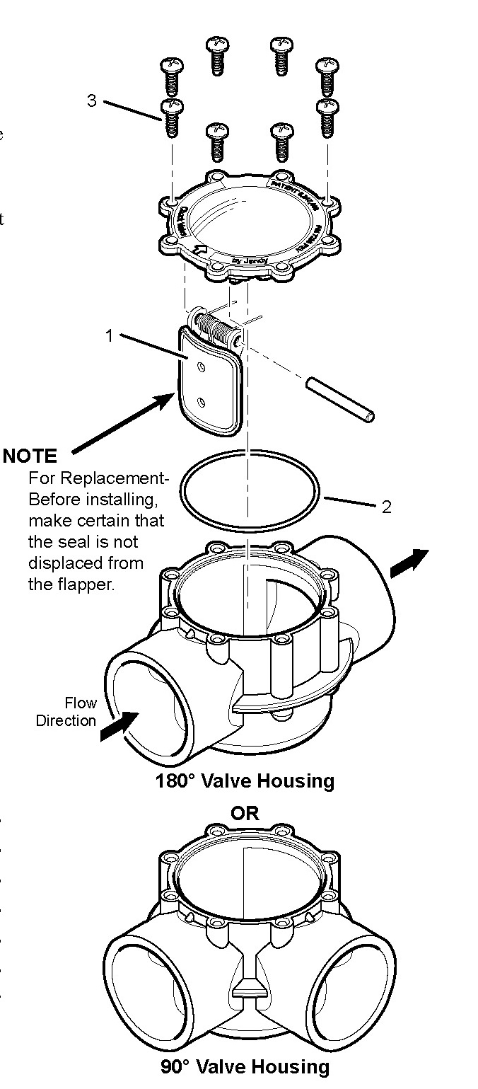
Both designs share the same swing/spring mechanism and clear inspection lid for easy servicing.
Identify the Best Installation Location for Your Application
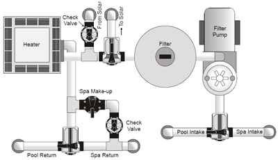
Where you place the valve determines how effectively it prevents backflow and protects your equipment.
Install Before Chlorinators to Block Chemical Damage
Concentrated chlorine flowing backward can destroy heaters, pumps, and filters when the system shuts off.
Place the Jandy check valve between the filter or heater and the chlorinator. Flow direction should move from filter to valve to chlorinator to pool. This positioning stops chemically treated water from re-entering sensitive mechanical components.
Always confirm the flow arrow on the valve body points in the correct direction before gluing.
Add a Check Valve to Solar Heating Lines
Solar panels mounted 8 feet or higher above the pump will drain back into the equipment pad when circulation stops. This causes dry pipes, air locks, and lost heating efficiency.
Install the valve on the supply line leading up to the solar panels. Position it near the equipment pad for easy access. Use the 2.5″ x 3″ model when connecting to a 3HP Stealth Pump. This keeps the solar loop primed and ready for immediate heat capture.
Prevent Spa Water from Siphoning into the Pool
When a spa sits higher than the pool, gravity pulls water downward the moment the pump stops. This leads to overflow, lost prime, and frustrated owners.
Place a check valve in the supply line feeding the spa. Install it before any diverter valves or manifolds. Choose a 90° model if space near the spa pad is limited. The valve holds water in the spa and preserves proper water levels.
Maintain Water Feature Reservoir Volumes
Fountains, cascades, and elevated basins drain back into the main pool whenever the pump cycles off.
Install the check valve in the pump discharge line leading to the water feature. Position it before any elevation rise in the piping. Pair the valve with a timer or automation system for consistent operation. This keeps the feature’s reservoir full and ready for the next cycle.
Follow Step-by-Step Jandy Check Valve Installation Procedures
Once you have selected the right model and location, proper installation ensures a leak-free, long-lasting connection.
Shut Down Power and Depressurize the Line
Safety comes first. Turn off the pool pump at the breaker and close any isolation valves in the plumbing.
Open a nearby air bleeder or loosen a union fitting to drain pressure from the line. Working on a depressurized system prevents accidental flooding and chemical spray.
Dry-Fit All Components Before Applying Cement
Assemble the valve and adjacent fittings without adhesive to verify alignment and orientation.
Confirm the flow arrow points toward the pool, spa, or water feature. Check that the 90° or 180° model fits the available space. Make sure the valve aligns properly with existing PVC pipes. Adjust as needed to avoid stress on joints before any glue is applied.
Prepare and Glue CPVC Connections Properly
Gather these supplies before starting:
– PVC primer (purple)
– CPVC-rated cement
– Measuring tape
– Pipe cutter
Follow these steps for a secure bond:
- Cut pipes square and deburr all edges
- Dry-fit all pieces, including unions for future service
- Apply primer to both the pipe exterior and fitting interior
- Apply cement immediately after priming
- Insert pipe into fitting with a quarter turn and hold for 15 seconds
- Wipe away excess cement with a clean rag
Never glue the clear lid. It must remain removable for inspection and cleaning. Allow 2 hours of curing time before pressurizing the system.
Test the System After Reassembly
Once the glue has set, reinstall the clear lid and red seal plate by hand. Turn on power and open all isolation valves.
Run the system for 5 minutes and watch through the clear lid. The valve should open during flow and snap closed when the pump stops. If the seal does not close fully, shut down and check for debris or misalignment.
Perform Routine Inspections and Cleaning

Even the toughest CPVC valves need periodic attention to stay functional in demanding pool environments.
Conduct Monthly Visual Inspections Through the Clear Lid
The transparent lid allows quick checks without disassembly. Look for debris caught in the swing mechanism, cracks or warping on the red seal plate, and any signs of corrosion or discoloration.
A simple glance during routine maintenance catches most issues before they become problems.
Clean the Valve When Flow Becomes Restricted
Reduced water output, a valve that stays open after shutdown, or gurgling air noise all signal the need for cleaning.
Follow this process to restore full function:
- Shut off the pump and relieve line pressure
- Unscrew the clear lid by hand
- Remove the red seal plate and swing arm
- Rinse all parts with clean water
- Check spring tension and replace if weak
- Reinstall components and test operation
Most users complete this cleaning in under 10 minutes thanks to the tool-free design.
Avoid Common Installation Mistakes That Compromise Performance
Even experienced technicians can make errors that reduce valve effectiveness or cause premature failure.
Installing the Valve Backward
Ignoring the flow arrow is the most frequent error. A reversed valve will not open during operation, causes immediate pressure drop, and may damage the swing mechanism. Always double-check that the arrow points in the direction of system flow.
Overtightening the Clear Lid
The lid is designed for hand-tightening only. Using a wrench can crack the CPVC housing, warp the seal, and prevent future access. Tighten only until resistance is felt.
Skipping Unions for Future Service Access
Gluing the valve directly into the line makes removal difficult during repairs or upgrades. Install slip unions on both sides of the valve to allow easy removal without cutting pipes. This saves significant time during future maintenance.
Mixing Dissimilar Materials Without Proper Fittings
The Jandy valve uses CPVC, but some systems include PVC or metal piping. Always use appropriate transition fittings when connecting different materials. Never directly glue dissimilar plastics together, and allow for thermal expansion in long pipe runs.
Maximize Flow Performance and Minimize Head Loss
The Jandy 7307 is engineered for high-flow applications up to 170 GPM. Proper placement and piping choices help you achieve rated capacity.
Achieve Maximum Flow Capacity
Use the 2.5″ x 3″ model with 3HP Stealth Pumps for best results. Avoid sharp bends or undersized pipes downstream of the valve. Keep the valve in a straight run whenever possible to reduce turbulence and preserve head pressure.
Reduce Head Loss for Better Efficiency
The valve’s low-resistance design maintains system efficiency when installed correctly. Install vertically or horizontally, as both orientations work well. Avoid mounting near elbows or tees that create swirl patterns. Keep inlet and outlet piping straight for at least 6 inches on each side.
Troubleshoot Common Operational Issues
Even with perfect installation, problems can occasionally arise. Quick diagnosis helps restore function fast.
Valve Fails to Close Completely
Debris in the seat is the most common cause. Shut down and clean the internal components. A worn red seal requires replacement of the seal plate kit. A weak spring needs an OEM replacement to restore proper closing force.
Inspect visually first through the clear lid. Most issues are immediately visible without disassembly.
Gurgling or Air Noise After Shutdown
Incomplete sealing causes air noise after the pump stops. Check for a warped or cracked seal plate. Verify correct orientation with the flow arrow pointing forward. Ensure the lid is properly seated and hand-tightened.
If noise persists, disassemble the valve and inspect the hinge pin for wear or damage.
No Flow During Pump Operation
The valve may be installed backward, requiring reversal of orientation. A stuck swing arm needs disassembly to free the mechanism. Glue intrusion during installation can block the swing path and requires careful flushing to remove.
Always test manually by lifting the swing arm to confirm free movement before reassembly.
Integrate the Check Valve with Smart Pool Automation
Advanced pool systems benefit from pairing the check valve with modern controls for enhanced safety and efficiency.
Connect with Jandy iQ3 or AquaLink Systems
Schedule solar heating only during peak sun hours to maximize energy savings. Automate spa fill cycles with flow verification for consistent water levels. Receive alerts if backflow is detected through compatible flow sensors.
The check valve operates passively but strengthens automated safety protocols throughout the system.
Add a Flow Meter for Real-Time Monitoring
Monitor GPM in real time to detect early signs of clogging. Verify 170 GPM performance during peak demand. Identify pump degradation over time through trending data.
Use this information to schedule preventive maintenance before failures interrupt pool or spa operation.
Frequently Asked Questions About Jandy Check Valve Installation
Where should a Jandy check valve be installed on a chlorinator line?
Install the valve between the filter or heater and the chlorinator. This placement prevents concentrated chlorine from flowing backward into sensitive equipment when the pump shuts off. The flow arrow must point away from the filter toward the chlorinator.
What size Jandy check valve do I need for a 3HP Stealth Pump?
Use the 2.5″ x 3″ model specifically engineered for the Jandy Pro Series 3HP Stealth Pump. This size maintains the 170 GPM flow capacity and minimizes head loss for optimal high-flow performance.
How do I prevent solar panels from draining back into the pool?
Install a Jandy check valve on the supply line leading up to the solar panels. Panels mounted 8 feet or higher above the pump will drain by gravity without a valve. Place the valve near the equipment pad for easy access and service.
Can I install a Jandy check valve vertically?
Yes, both vertical and horizontal installations are acceptable. The swing/spring mechanism functions properly in either orientation. Choose the position that best fits your equipment pad layout and plumbing path.
How often should I inspect my Jandy check valve?
Perform a visual inspection through the clear lid monthly. Look for debris, seal damage, or discoloration. Clean the internal components whenever you notice reduced flow, incomplete sealing, or air noise after shutdown.
What is the maximum flow rate for the Jandy 7307 check valve?
The Jandy Pro Series Check Valve (Model #7307) handles flow rates up to 170 GPM. This makes it ideal for high-flow applications including spas, water features, and large pool circulation systems.
Key Takeaways for a Successful Jandy Check Valve Installation
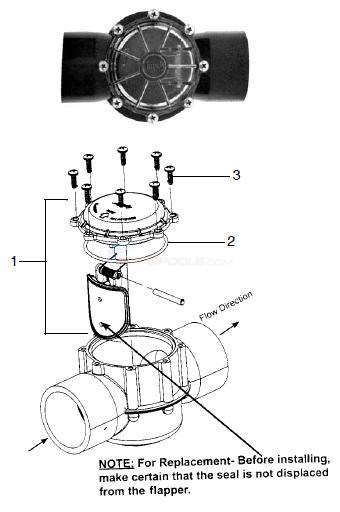
A proper Jandy check valve installation protects your pool equipment, prevents water loss, and maintains system efficiency across multiple applications. Choose the correct size (2″x2.5″, 1.5″x2″, or 2.5″x3″) and angle (180° or 90°) based on your plumbing layout and pump specifications.
Place the valve in the correct location for your application: before chlorinators to block chemical backflow, on solar supply lines to prevent drain-back, on spa feeds to stop siphoning, or before water features to maintain reservoir levels. Follow proper PVC gluing procedures, respect the 2-hour cure time, and always verify flow direction using the arrow on the valve body.
Leverage the clear lid for quick monthly inspections and clean debris as needed using the tool-free disassembly design. Avoid common mistakes like backward installation, overtightening the lid, or skipping unions for future service access.
For official installation instructions, refer to document H0292100 or contact Jandy Support at 1.800.822.7933. With a 4.9-star user rating and rugged CPVC construction, the Jandy 7307 delivers reliable backflow protection for high-flow pools, spas, and solar-heated systems.