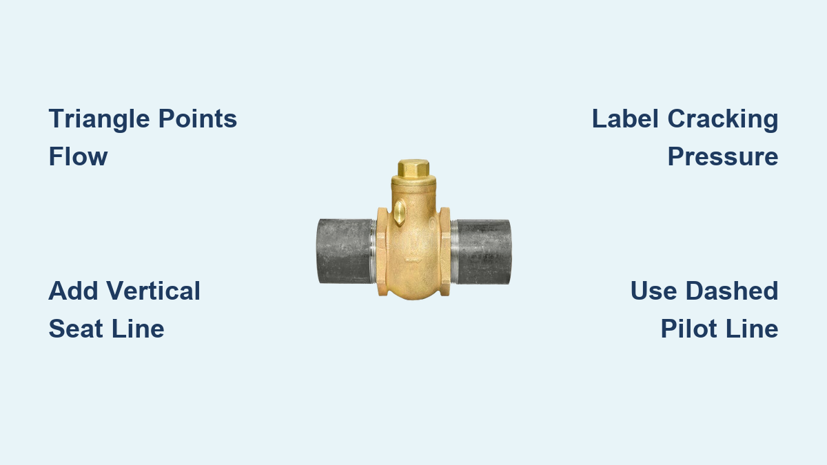
You’re sketching a hydraulic circuit, reviewing a process diagram, or laying out a piping schematic, and you need to know how to draw a check valve the right way. A single reversed triangle can flip the entire function of a system, leading to pump damage or cylinder drift. The symbol may look simple, but its orientation, line weight, and context carry real engineering meaning. This guide walks you through the step-by-step process of drawing standard and advanced check valve symbols, explains the key variations, and shows you how to avoid the most common drawing mistakes.
Whether you’re a student, technician, or working engineer, mastering how to draw a check valve ensures your schematics communicate clearly across teams and standards. Below you’ll find practical drawing steps, troubleshooting tips, and best practices grounded in ISO, ANSI, and ASME conventions.
Standard Check Valve Symbol
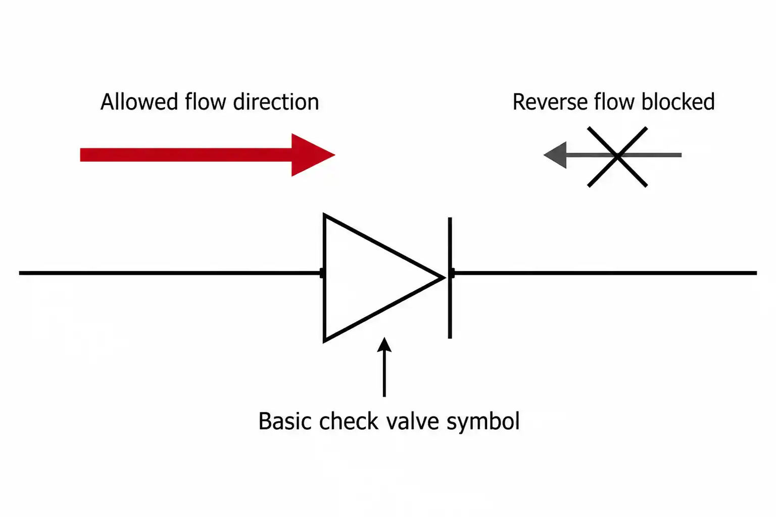
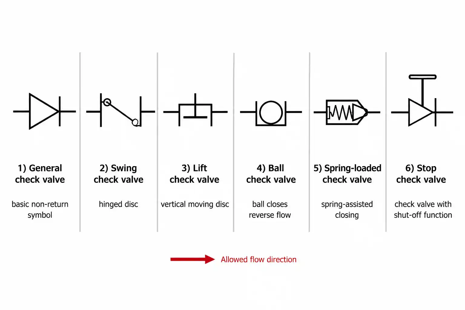
The basic check valve symbol is the foundation of every schematic you’ll create. It uses a triangle and a vertical line to show direction and blocking action at a glance.
Triangle Points Toward Flow Direction
Draw a triangle with its apex pointing in the direction of allowed flow. The base sits vertical and perpendicular to the pipeline. If fluid should move left to right, the triangle points to the right. Reverse the direction, and you reverse the valve’s function completely.
Add the Vertical Seat Line
Place a straight vertical line touching the triangle’s apex. This line represents the seat where the disc or ball seals to stop reverse flow. The triangle pushes toward this line during forward flow but cannot cross it going backward.
Connect to the Pipeline
Extend two horizontal lines on either side of the symbol to represent the inlet and outlet pipes. The inlet connects to the triangle’s base, and the outlet extends from the vertical seat line. Keep these lines continuous and aligned with the rest of your drawing.
Pro Tip: Use bold lines for process piping and thinner lines for the valve symbol itself. This visual hierarchy helps readers scan your schematic quickly.
Spring-Loaded Check Valve
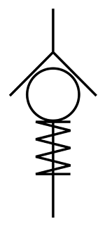
When systems need faster closure or operation under low differential pressure, a spring-loaded check valve is the standard choice.
Add a Zig-Zag Spring Symbol
Draw a zig-zag line near the triangle, typically on the side opposite to flow. This represents the internal spring that keeps the valve closed until forward pressure exceeds the cracking pressure rating.
Label the Cracking Pressure
Always annotate the spring setting next to the symbol. For example, write “5 psi” or “0.3 bar” beside the spring. This tells installers and maintenance teams the exact pressure needed to open the valve.
Common Mistake: Skipping the cracking pressure label leads to wrong valve selection during repairs. Always include it.
Pilot-Operated Check Valve
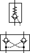
Used in hydraulic circuits to lock cylinders in position, pilot-operated check valves allow reverse flow only when activated by external pressure.
Draw a Dashed Pilot Line
Add a dashed line entering the side of the valve symbol. This indicates the pilot signal that, when pressurized, forces the internal piston open and permits reverse flow.
Use Connection Dots
Where the pilot line taps into the main system, place a solid black dot to show a physical connection. No dot means lines cross without connecting, a critical distinction in complex schematics.
Represent Double Check Configurations
For load-holding circuits, two pilot-operated check valves are often shown back-to-back in a sandwich plate layout. Each has its own pilot line, allowing bidirectional control when energized and locking flow when de-energized.
Pilot-to-Close Check Valve
Less common but vital in safety circuits, this valve closes when pilot pressure is applied.
Show the Pilot Line Above the Closing Element
Draw the dashed pilot line entering from the top of the valve symbol, above the ball or poppet. This visually distinguishes it from pilot-to-open designs.
Understand Functional Reversal
Applying pilot pressure forces the valve shut, stopping flow even if forward pressure exists. This is useful in emergency stop systems or isolation circuits where positive closure is required.
Check-Stop Valve Combination
When manual shutoff and automatic backflow protection are both needed, a check-stop valve handles both jobs.
Combine Globe and Check Symbols
Draw a globe valve symbol (a circle with a horizontal line and stem) and integrate the triangle-and-line check valve inside or adjacent to it. This creates a single composite symbol.
Indicate Dual Functionality
Label the symbol clearly as “Check-Stop” or “Stop-Check” to prevent confusion. Without a label, readers may assume it’s just a standard isolation valve.
Check Valve vs. Relief Valve: Spot the Difference
These symbols look similar but serve opposite purposes. Mixing them up can cause serious system damage.
Check Valve Flow Path
A check valve sits in-line with actuators. Flow moves through the valve toward cylinders or motors, and no pilot line senses system pressure to open it.
Relief Valve Output to Tank
The relief valve symbol includes a dashed pilot line connected to the high-pressure side. Its outlet directs fluid to the tank, not to work components.
Quick Test: If fluid goes to the reservoir when the valve opens, it’s a relief valve. If it allows forward flow in a working loop, it’s a check valve.
P&ID Integration Rules
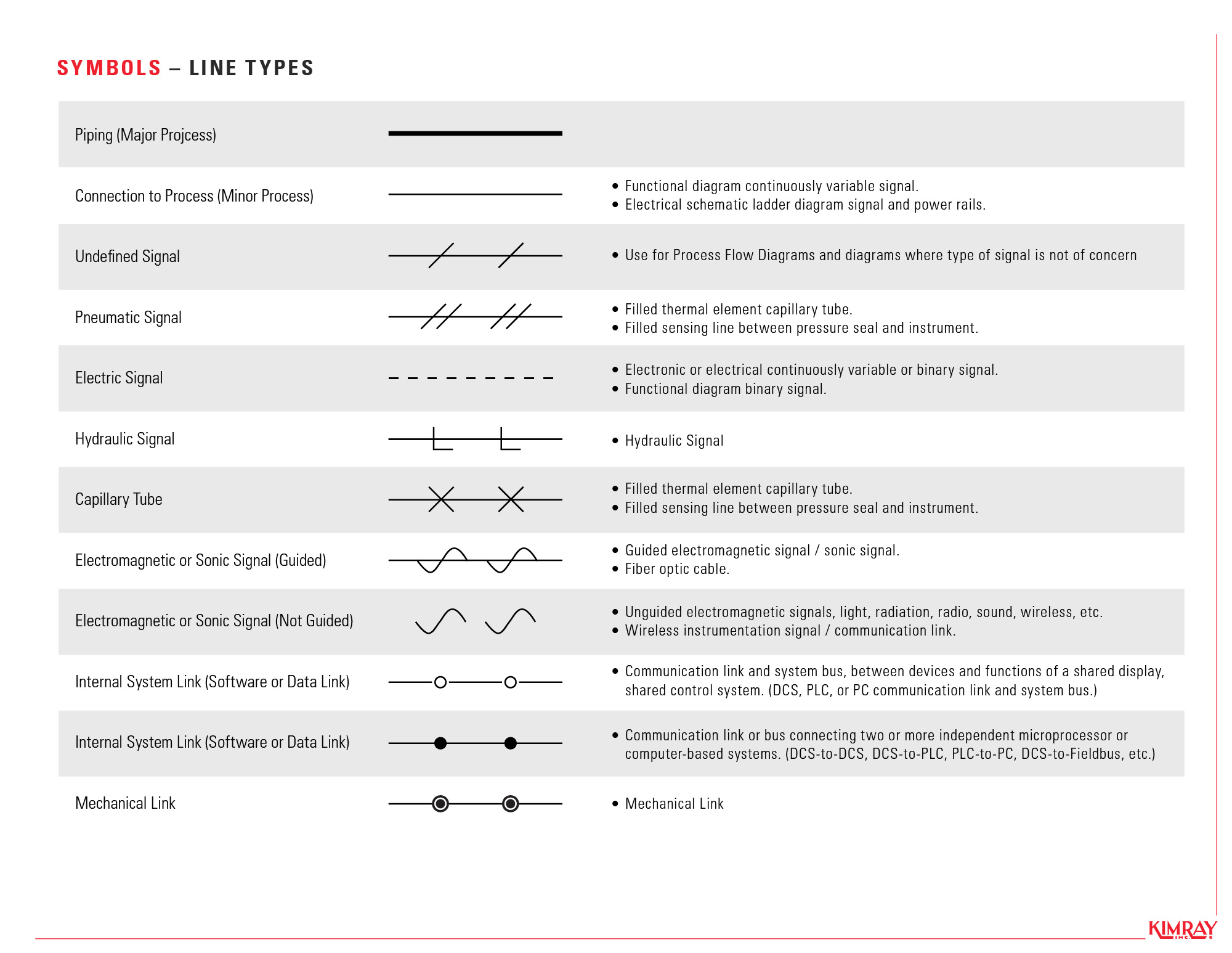
In process diagrams, every line and symbol carries meaning beyond just function.
Use Correct Line Types
- Solid bold line for process piping
- Dashed line for hydraulic pilot signals
- Dashed with dots for pneumatic control
- Solid with lightning bolt for electric signals
Show End Connections
Indicate how the valve attaches to the pipe:
– Perpendicular lines at the ends signal a flanged connection
– Short diagonal lines signal threaded or welded connections
Annotate Valve States
Although most check valves are automatic, label any manual override or non-standard state:
– “NC” for normally closed (rare)
– “Manual Override” if applicable
Common Physical Types and Symbol Links
Knowing the real-world valve helps you choose the right symbol or annotation.
Swing Check Valve
Uses a hinged disc. Draw the standard symbol and note “Swing” if clarity is needed. Best for low-velocity lines.
Lift Check Valve
Has a vertical disc or ball mechanism. Often spring-loaded. Use the spring symbol and label cracking pressure.
Ball Check Valve
Common in small hydraulic lines. Same symbol as standard, but may be drawn smaller in detailed schematics.
Diaphragm Check Valve
Used with corrosive fluids. Represent with the standard symbol and add a material note like “PTFE Lined” or “Diaphragm Type.”
Four-Valve Box Circuit
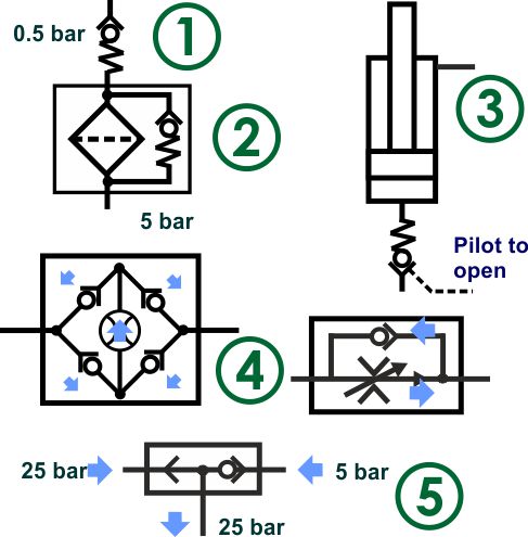
A clever configuration using four check valves keeps flow unidirectional through a single control valve.
Draw the Box Layout
Place four check valves around a central flow control valve, forming a diamond or box shape. Each valve points to route flow through the center valve in the same direction.
Explain Bidirectional Input
Whether flow enters from the left or right, two check valves open to direct fluid through the control valve in one fixed direction.
Benefit: One flow control setting regulates cylinder speed in both directions, eliminating the need for duplicate valves.
Troubleshooting Tips from Symbols
The symbol itself can help you predict or diagnose problems.
Backward Installation
If a pump won’t prime or pressure won’t build, check the triangle direction. A reversed symbol means the valve is blocking forward flow.
Cylinder Drift
If a hydraulic cylinder slowly lowers under load, the pilot-operated check may be leaking. Inspect the symbol for pilot line integrity and spring condition.
Water Hammer
Rapid closure of swing check valves causes pressure spikes. Look for spring-loaded or dashpot-dampened symbols in high-velocity systems.
Drawing Best Practices Summary
Accuracy and consistency prevent misinterpretation across teams and projects.
Verify Flow Direction First
Always confirm the intended flow path before drawing the triangle. One wrong point changes everything.
Use Standard Geometry
Stick to the triangle-and-line format. Avoid custom or artistic interpretations that confuse readers.
Maintain Line Weight Hierarchy
- Thick lines for main process flow
- Medium lines for valve bodies
- Thin or dashed lines for pilot and control signals
Annotate Critical Details
Include cracking pressure, pilot function (open or close), and material or type if non-standard.
Cross-Check Against Standards
Refer to ISO 1219 for fluid power or ANSI/ISA S5.1 for P&IDs to ensure full compliance.
Frequently Asked Questions About Drawing Check Valves
What is the standard symbol for a check valve?
The standard check valve symbol is a triangle pointing toward a vertical line. The triangle’s apex indicates the direction of allowed flow, and the vertical line represents the seat that blocks reverse flow.
How do you show a spring-loaded check valve on a drawing?
Add a zig-zag line near the triangle to represent the internal spring. Label the cracking pressure next to the symbol so installers know the minimum pressure needed to open the valve.
What is the difference between a check valve and a relief valve symbol?
A check valve has a triangle pointing toward a seat line with no external pilot signal. A relief valve includes a dashed pilot line connected to the high-pressure side and directs flow to the tank when open.
Why does check valve orientation matter in a schematic?
The triangle must point in the direction of allowed flow. Reversing it blocks forward flow instead of reverse flow, which can cause pumps to lose prime or cylinders to drift under load.
How do you draw a pilot-operated check valve?
Start with the standard triangle-and-line symbol, then add a dashed pilot line entering from the side. Place a solid black dot where the pilot line connects to the main system.
What standards govern check valve symbols?
ISO 1219 governs fluid power symbols, while ANSI/ISA S5.1 covers P&ID conventions. ASME standards also apply in many process and piping contexts.
Key Takeaways for Drawing Check Valves with Confidence
Learning how to draw a check valve comes down to three essentials: master the triangle-and-line foundation, respect flow direction, and annotate every variation clearly. The standard symbol works for most situations, but spring-loaded, pilot-operated, and check-stop versions require extra details to communicate function.
Before you finalize your next schematic, review each check valve symbol for correct orientation, proper line weights, and complete annotations. Cross-reference your drawing against ISO 1219 or ANSI/ISA S5.1 to catch any errors before installation. With these habits in place, your schematics will communicate clearly, prevent costly mistakes, and hold up to professional scrutiny.


