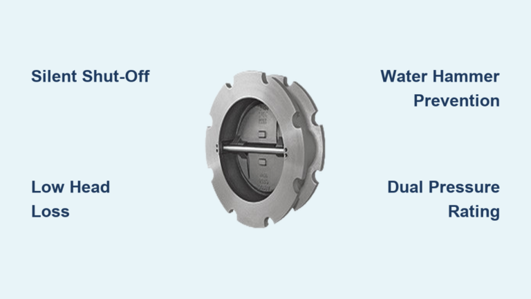
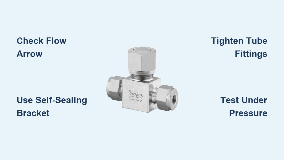
A single backward-installed check valve can shut down an entire production line. Many technicians discover this only after leaks appear, pressures drop, or contamination ruins a sensitive process. Swagelok check valve installation demands precision from valve selection through final commissioning, especially when working with adjustable cracking pressures or ultrahigh-purity systems.
This guide covers every stage of Swagelok check valve installation, including series selection, flow orientation, tube fitting assembly, cracking pressure adjustment using a self-sealing angle bracket, pressure testing, and long-term maintenance. You will learn practical techniques that prevent the most common installation failures and ensure reliable, leak-free operation across industrial, hydrogen, and semiconductor applications.
Choose the Correct Swagelok Check Valve Series
/Swagelok%20Northern%20California%20Resource%20Collections%20440x340%20Check%20Valves%20(1)%20(1).png?width=300&name=Swagelok%20Northern%20California%20Resource%20Collections%20440x340%20Check%20Valves%20(1)%20(1).png)
Selecting the right valve series is the foundation of a successful installation. Each Swagelok series is engineered for specific pressure ranges, temperatures, fluid types, and purity standards.
Match Valve Type to Application Demands
Different operating environments require different valve architectures. Match your system conditions to the appropriate series:
- 50 Series (Lift Check): Rated to 6,000 psig and temperatures up to 900°F. Contains no springs or elastomers, making it ideal for high-temperature thermal stability applications.
- C, CP, CH, CPA Series (Poppet): General industrial service up to 6,000 psig. Available in 316 stainless steel or brass with fixed or adjustable cracking pressures from 1 to 25 psi.
- FK and IPT Series (High Pressure): Rated up to 60,000 psig and 1,000°F. FK models are optimized for hydrogen service with reliable shut-off.
- CW Series (All-Welded): 316L stainless steel construction with no threaded joints. Forward flow initiates below 2 psig differential for low-pressure high-purity systems.
- CHP Series (Ultrahigh-Purity Polymer): Modified PTFE wetted parts meeting SEMI F57-0301 standards for semiconductor manufacturing.
- XS Series (Excess Flow): Automatically shuts off flow during downstream line rupture. Critical safety component for hazardous fluid systems.
Confirm Material Compatibility with Process Media
Material selection prevents corrosion, contamination, and premature failure. Choose based on your specific fluid chemistry:
- 316 or 316L Stainless Steel: Standard choice for most industrial and high-purity systems
- Brass: Suitable for non-corrosive fluids such as air or water
- Alloy 625: Excellent resistance to oxidizing and non-oxidizing acids
- Alloy 825: Resistant to sulfuric and phosphoric acids
- Alloy 2507 Super Duplex: Superior corrosion resistance in chloride-rich environments
- Modified PTFE: Best for ultrahigh-purity gases and aggressive solvents
Always consult Swagelok chemical compatibility charts before finalizing your material selection.
Verify Pressure, Temperature, and Flow Requirements
Undersized valves cause excessive pressure drop while oversized valves create flow instability. Use Swagelok’s Cv calculator to size the valve properly for your specific flow rate. Confirm that maximum working pressure and temperature ratings exceed your system’s peak operating conditions. For high-purity CW and CHP series, ensure forward flow requirements align with the sub-2 psig activation threshold.
Verify Flow Direction and Valve Orientation
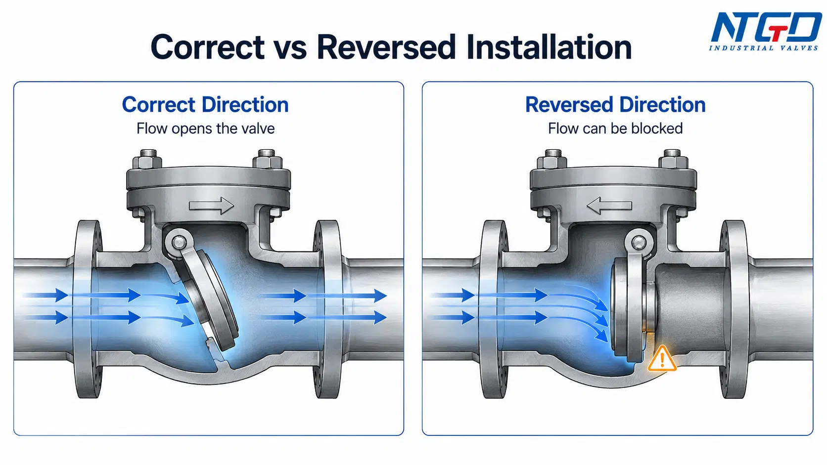
Installing a check valve backward renders it completely useless. Correct orientation is non-negotiable for proper Swagelok check valve installation.
Identify Flow Direction Markings
Every Swagelok check valve displays clear flow direction indicators on the body. Look for an arrow stamped into the valve housing. This arrow points in the direction of allowed forward flow. Never install against the arrow direction, as reverse orientation prevents the valve from opening and risks internal damage.
Position in Accessible, Vibration-Free Locations
Strategic placement simplifies future maintenance and extends valve life. Avoid tight bends or crowded piping zones where access is restricted. Mount the valve in-line with minimal mechanical stress on end connections. Secure nearby tubing with proper supports to reduce vibration, which can cause premature wear or chatter during operation.
Prevent Contamination During Handling
Cleanliness matters most in high-purity applications. Cap all open ends before installation begins. Use lint-free wipes and clean tools throughout the process. For CW and CHP series, avoid touching sealing surfaces with bare hands to prevent particulate contamination.
Prepare Tools and Follow Safety Protocols
Proper preparation prevents leaks, component damage, and personal injury during Swagelok check valve installation.
Gather Required Installation Tools
Assemble these tools before beginning work:
- Swagelok tube fitting cutters and deburring tool
- Tube fitting gap inspection gauge
- Two wrenches for proper tube nut tightening
- Torque wrench for NPT or high-pressure connections
- Clean lint-free cloths
- Pressure testing equipment including gauge and pump
- Self-sealing angle bracket tool for adjustable valve calibration
Never apply pipe dope or thread sealant to Swagelok tube fittings or face seal connections. These fittings create their own metal-to-metal seal.
Follow Essential Safety Procedures
Safety must come first in every installation. Depressurize and purge the system completely before starting work. Wear appropriate PPE including safety glasses, gloves, and protective clothing. Work in a well-ventilated area, especially when handling hydrogen or toxic gases. Confirm that valve and system pressure ratings exceed your maximum operating pressure before commissioning.
Install Swagelok Tube and Threaded Connections

Swagelok valves ship with various end connection types. Each requires specific installation techniques to achieve leak-free performance.
Swagelok Tube Fitting Installation Procedure
Follow this three-step process for 1/4 inch to 1/2 inch tube fittings:
-
Cut and deburr the tubing using a Swagelok tube cutter for a square cut. Remove all internal and external burrs with a deburring tool, then clean the tube end thoroughly.
-
Assemble the fitting components by sliding the nut, then the ferrule onto the tube. Insert the tube fully into the fitting body until it seats against the shoulder. Mark the tube at the body shoulder to verify complete insertion.
-
Tighten to specification by hand-tightening the nut until snug. Hold the fitting body with one wrench while turning the nut with a second wrench. For 1/4 inch tubing, tighten 1.25 turns past finger-tight. For 3/8 inch and 1/2 inch tubing, tighten 1.5 turns. Use a torque wrench when specified.
NPT Thread Installation Method
For valves with NPT end connections, apply thread sealant only to the male threads. Use PTFE tape or approved pipe dope without contaminating the bore. Tighten to manufacturer-specified torque values. Align carefully during initial threading to avoid cross-threading damage.
Adjust Cracking Pressure on Adjustable Valve Models
C, CP, and CH series valves with adjustable cracking pressures require precise calibration. Traditional methods are slow and error-prone, but advanced tools dramatically improve accuracy.
Understand Cracking Pressure Fundamentals
Cracking pressure is the minimum upstream pressure required to open the valve and initiate forward flow. Adjustable valves use a spring-and-nut compression system where tightening the nut increases cracking pressure. The standard adjustable range spans 1 to 25 psi, though some models allow custom calibration for specific applications.
Traditional Adjustment Method Limitations
The old approach requires repeated connect-disconnect cycles that waste time and introduce contamination risks. Technicians attach pressure source and gauge, pressurize to observe the opening point, then depressurize and disconnect hoses. They adjust the nut with a hex tool, reconnect, and retest. This cycle repeats until the setting remains stable over three consecutive tests. Each disconnection cycle introduces potential leak paths and contamination opportunities.
Use the Self-Sealing Angle Bracket for Live Adjustment
The self-sealing angle bracket revolutionizes Swagelok check valve installation by enabling real-time adjustment without breaking the pressure seal.
How the Device Functions
A hex-tipped rod inserts into the valve’s adjustment nut through a T-fitting. A spring-loaded O-ring creates an automatic seal around the rod as pressure is applied. A custom slot in the hex tip allows fluid to flow around the tool, keeping pressure active throughout adjustment. A stopper clip and shaft collar prevent rod disengagement under pressure, ensuring operator safety.
Step-by-Step Calibration Procedure
-
Attach the device to the check valve using compatible adapters for CA or CPA series configurations. Verify that seals are intact and O-rings are properly lubricated.
-
Insert the adjustment rod by lowering the hex rod into the adjustment nut. The O-ring seals automatically as system pressure is applied.
-
Apply system pressure gradually while monitoring the downstream gauge for flow initiation at the cracking point.
-
Adjust in real time by turning the handle to rotate the adjustment nut. Observe the gauge continuously. Tighten to increase cracking pressure or loosen to decrease it. Make small, incremental turns for precision.
-
Lock the setting by tightening the lock nut once the target pressure is reached. The shaft collar prevents the rod from turning during this critical step.
-
Verify and remove by confirming cracking pressure holds stable over three cycles. Depressurize the system, then remove the tool.
This method reduces adjustment time by up to 70 percent while improving accuracy, especially for tight-tolerance applications where a few PSI of error matters.
Pressure Test and Commission the Installed System
Verification testing confirms that Swagelok check valve installation meets performance specifications before full operation begins.
Perform Leak and Function Testing
Follow this systematic testing sequence:
-
Isolate the test section by closing upstream and downstream isolation valves, then depressurize and vent completely.
-
Pressurize gradually using inert gas such as nitrogen for initial testing. Increase pressure slowly to 110 percent of normal operating pressure.
-
Check all joints for leaks by applying leak detection fluid to tube fittings, body connections, and seals. Listen for hissing sounds that indicate high-pressure leaks.
-
Test valve function by pressurizing the upstream side and confirming the valve opens at the set cracking pressure. Apply back pressure and verify complete sealing with no reverse flow. For XS series excess flow valves, simulate rupture by rapidly opening a downstream valve to confirm automatic shut-off.
Document Installation Details for Compliance
Record critical information for future maintenance and regulatory compliance:
- Valve model number and serial number
- Final cracking pressure setting
- Installation date
- Technician name
- Test results including pressure levels and leak rates
For high-purity or safety-critical systems, maintain logs according to ISO or SEMI standards.
Avoid Common Installation Mistakes
Small errors during Swagelok check valve installation create big problems later. Watch for these frequent issues.
Incorrect Flow Orientation
Symptom: No flow occurs even at high system pressure. Fix: Double-check the arrow on the valve body before final tightening. Prevention: Mark flow direction on the pipe before installing the valve.
Overtightened Tube Fittings
Symptom: Cracked ferrule, tube damage, or persistent leaks. Fix: Replace damaged fittings rather than attempting to re-tighten. Prevention: Use a torque wrench and follow Swagelok’s turn-to-torque specifications.
Contaminated Sealing Surfaces
Symptom: Micro-leaks or particulate contamination in high-purity systems. Fix: Disassemble, clean thoroughly, and reinstall. Prevention: Wear gloves, cap all lines, and use only clean tools.
Poor Cracking Pressure Calibration
Symptom: Valve opens too early or fails to open at all. Fix: Readjust using the self-sealing bracket method. Prevention: Calibrate under actual system conditions rather than bench testing alone.
Maintain and Service Check Valves Long-Term
Swagelok valves are built for durability, but scheduled maintenance extends service life and prevents unexpected failures.
Schedule Regular Inspection Intervals
Inspect valves every six months or after significant pressure cycles. Check more frequently in high-vibration or high-temperature zones where wear accelerates. Replace seals immediately if system media is corrosive or abrasive.
Replace Wear Components Using Spare Parts Kits
Poppet-style valves in the C, CP, and CH series support internal component replacement. Order spare parts kits containing springs, seals, poppets, and deflector caps. Replace springs when cracking pressure drifts from specification. Change seals during reconditioning or when extrusion damage becomes visible. Inspect poppets and deflector caps for scoring or wear patterns.
The 50 series contains no springs or elastomers, eliminating these wear items entirely and making it the preferred choice for high-temperature applications where organic materials degrade.
Clean Thoroughly Before Reassembly
Flush internal passages with a compatible solvent before reassembly. Dry all components thoroughly using filtered air. Reassemble using clean tools and gloves to prevent contamination.
Frequently Asked Questions About Swagelok Check Valve Installation
What is the correct tightening specification for Swagelok tube fittings during check valve installation?
For 1/4 inch tubing, tighten the nut 1.25 turns past finger-tight with a wrench. For 3/8 inch and 1/2 inch tubing, tighten 1.5 turns past finger-tight. Always hold the fitting body with one wrench while turning the nut with a second wrench to prevent body rotation.
How do I identify the correct flow direction on a Swagelok check valve?
Every Swagelok check valve has an arrow stamped on the valve body indicating the direction of allowed forward flow. Install the valve so flow moves in the direction the arrow points. Installing against the arrow prevents the valve from opening and can cause internal damage.
What cracking pressure range is available on adjustable Swagelok check valves?
Adjustable C, CP, and CH series check valves offer cracking pressure settings from 1 to 25 psi (0.07 to 1.8 bar). The self-sealing angle bracket enables precise live adjustment without disconnecting pressure lines, improving both accuracy and installation speed.
Can Swagelok check valves be installed in high-purity semiconductor systems?
Yes. The CW series features all-welded 316L stainless steel construction with forward flow initiating below 2 psig differential. The CHP series uses modified PTFE wetted components and meets SEMI F57-0301 standards for ultrahigh-purity applications. Both series require careful contamination prevention during installation.
What is the maximum pressure rating for Swagelok check valves?
Standard series including 50, C, CP, CH, CPA, CW, and XS are rated to 6,000 psig (413 bar). The FK and IPT high-pressure series extend ratings up to 60,000 psig (4,134 bar) for extreme applications including hydrogen service.
How often should Swagelok check valves be inspected after installation?
Inspect check valves every six months or after significant pressure cycles. Increase inspection frequency in high-vibration, high-temperature, or corrosive service environments. Replace seals and springs when cracking pressure drifts from specification or when visible wear appears.
Key Takeaways for Successful Swagelok Check Valve Installation
Proper Swagelok check valve installation protects system integrity, prevents costly downtime, and ensures long-term reliability. Start by matching the valve series to your specific pressure, temperature, fluid, and purity requirements. Verify flow direction markings before tightening any connections, and use the correct tube fitting tightening specifications for your tubing size.
For adjustable cracking pressure models, the self-sealing angle bracket eliminates the tedious connect-disconnect cycle of traditional calibration methods. This tool enables real-time adjustment under live pressure, cutting installation time by up to 70 percent while improving accuracy. Always pressure test at 110 percent of operating pressure and document all settings for future maintenance reference.
Your next step: Review your current check valve inventory against the selection criteria in this guide. Identify any valves installed without verified flow direction markings or proper torque specifications, and schedule corrections before the next pressure cycle.