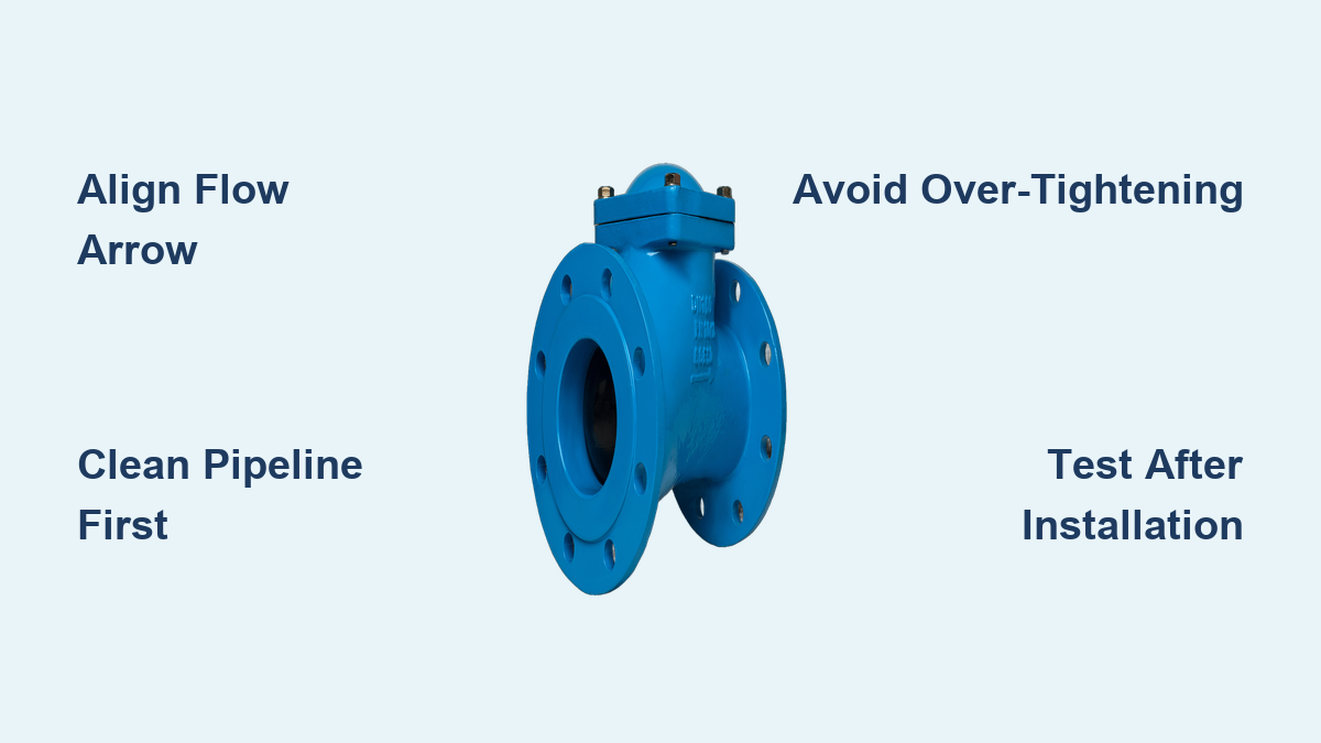
A single reversed arrow or a missed cleaning step can turn a routine valve job into a costly system failure. Many installers underestimate how sensitive ball check valves are to orientation, debris, and torque. Getting ball check valve installation right protects your system from leaks, water hammer, and premature wear.
This guide breaks down every critical phase of the process. You will learn how to prepare the pipeline, align flow direction, choose the correct mounting method, and verify performance through pressure and dynamic testing. These steps apply across industrial, sanitary, and high-pressure applications.
Pre-Installation: Clean and Inspect the Pipeline
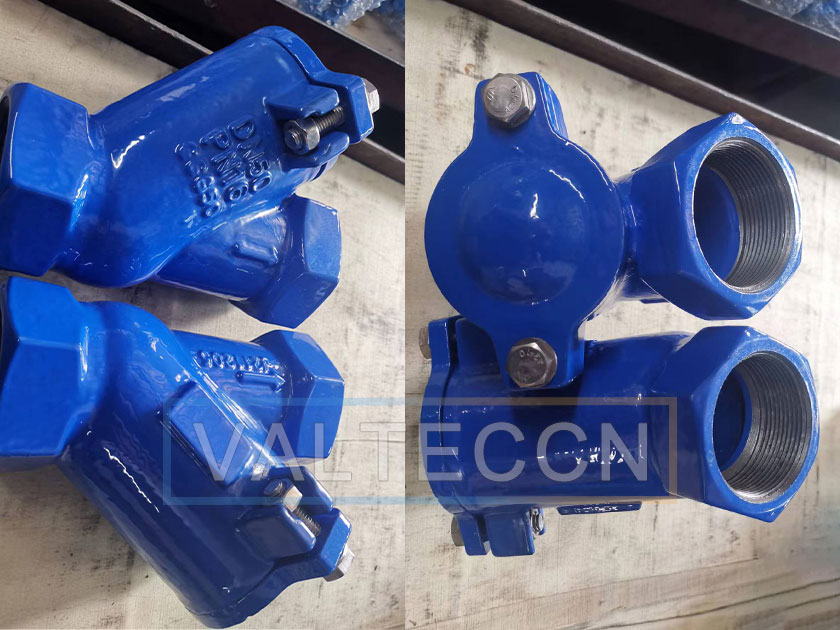
A clean pipeline and a verified valve are the foundation of a successful installation.
Remove Debris From the Pipeline
Flush the line with clean water or an appropriate cleaning fluid. Focus on both internal and external surfaces. Even small particles of rust, scale, or dirt can score the seat or block the ball from closing fully. In food-grade or pharmaceutical systems, this step is mandatory to meet sanitary standards.
Inspect pipe ends for burrs or deformation. Any irregularity can compromise the seal once the valve is mounted.
Inspect the Valve for Damage
Examine the valve body for cracks, dents, or casting flaws. Check the ball and seat for scratches, pitting, or distortion. If the valve uses a soft seat such as EPDM or Viton, confirm it is not warped or cracked.
Test the ball movement manually. Tilt the valve or gently blow air through it. The ball should lift freely and return to the closed position smoothly. A sluggish or stuck ball signals internal damage or contamination.
Confirm Gasket and Sealant Requirements
Review the manufacturer’s specifications for required gaskets, O-rings, or thread sealants. Some valves include integrated seals, while others need PTFE tape or liquid pipe dope on threaded ends. Apply sealant sparingly. Excess material can flake into the system and interfere with valve operation.
Flow Direction: Match the Arrow to Fluid Path
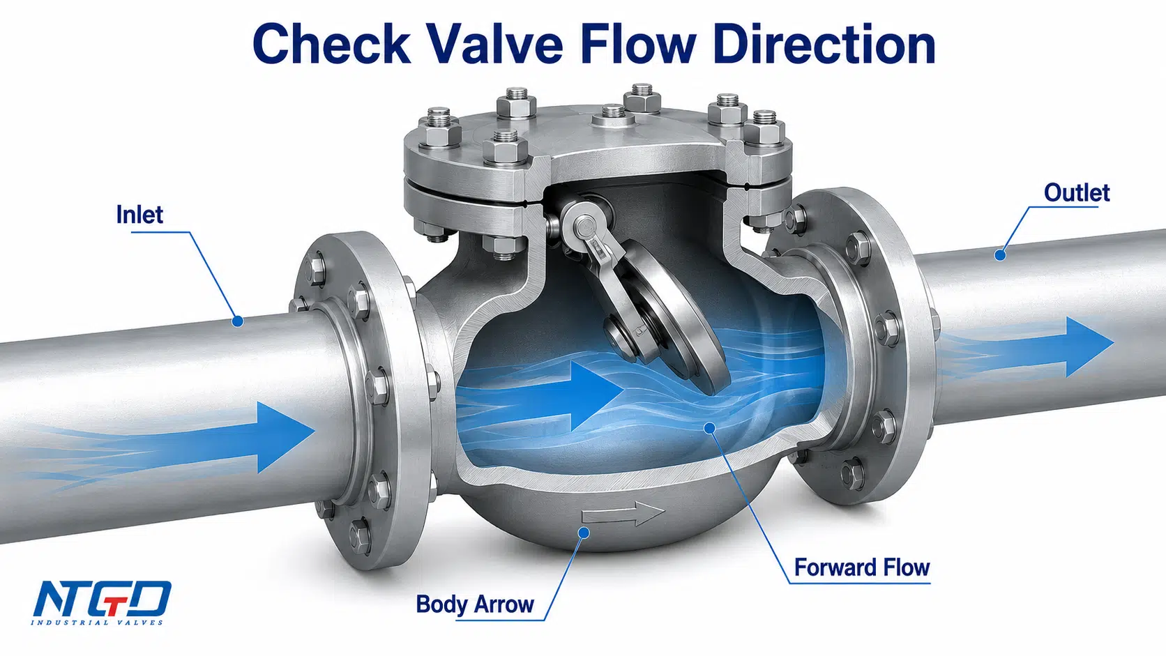
Correct flow direction is non-negotiable for ball check valve installation.
Locate and Align the Flow Arrow
Every ball check valve features a cast or stamped arrow on the body. This arrow points in the direction of forward flow. Align it precisely with the intended movement of fluid through the pipeline. The arrow must always point downstream.
Risks of Reverse Installation
Installing the valve backward creates immediate problems:
• The ball cannot lift during forward flow, blocking the line
• Continuous pressure on the wrong side damages the seat
• Water hammer and pressure surges become likely
• Catastrophic failure can occur under high pressure
Mark the valve with permanent tags during installation to avoid confusion in complex piping layouts.
Installation Orientation: Horizontal vs Vertical Lines
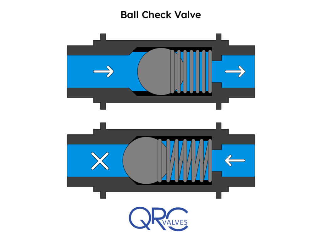
The correct orientation depends on valve design and disc movement mechanics.
Horizontal Pipe Installation
Most ball check valves are designed for horizontal lines. In this position, gravity helps return the ball to the seat when flow stops.
Position the valve so the ball sits above the pipe centerline when closed. Align flanges or threaded ends without forcing them. Use a level if needed to maintain proper alignment. This setup allows smooth forward flow and rapid closure, minimizing backflow risk.
Vertical Pipe Installation
Only use valves rated for vertical service in upright positions.
• For upward flow: install with the inlet at the bottom so flow pushes the ball upward
• For downward flow: avoid unless the valve has a spring-assist mechanism, since gravity may prevent proper opening
Installing a horizontally designed valve in a vertical line often causes slow closure, chattering, or seal failure. Always consult the manufacturer’s datasheet before choosing an orientation.
Mounting Methods: Flange, Threaded, Clamp, and Weld
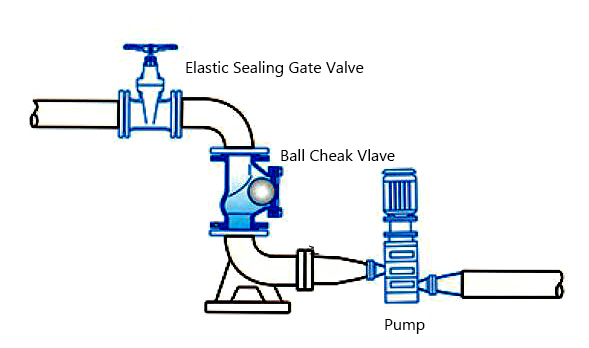
Select the connection method that matches your system requirements.
Flanged Connection Procedure
- Place the valve between aligned flanges
- Insert bolts hand-tight without fully securing them
- Center the gasket and confirm it does not protrude into the bore
- Tighten bolts in a crisscross pattern to distribute pressure evenly
- Apply final torque according to manufacturer specifications
Uneven tightening warps the valve body and causes leaks.
Threaded Connection Tips
- Apply PTFE tape or approved sealant to male threads only
- Wrap tape clockwise, three to five wraps maximum
- Screw the valve in by hand first to prevent cross-threading
- Use two wrenches: one to stabilize the pipe, one to tighten the valve
- Stop once the flow arrow is correctly oriented
Over-torquing cracks cast bodies, especially in brass or PVC valves.
Clamp-Style Valve Setup
Clamp connections are common in sanitary and quick-disconnect systems.
- Insert the wafer-style valve between two tri-clamp flanges
- Align the flow arrow with the system direction
- Slide the clamp ring over the joint and tighten the bolt evenly
- Confirm the gasket is centered and compressed uniformly
Misalignment can pinch the seal and cause premature failure.
Welded Joint Procedure
Welding is used in high-pressure, high-temperature, or critical process lines.
- Pre-fit the valve without welding to verify orientation and clearance
- Use low-heat welding techniques such as TIG to protect internal components
- Cool the valve body with wet rags or heat sinks during welding
- Follow ASME or applicable code standards for weld quality
Never weld a pressurized valve or one with the ball trapped in place.
Post-Installation Testing
Never energize a system without verifying valve function and seal integrity.
Conduct a Pressure Test
- Isolate the section containing the new valve
- Gradually pressurize to maximum operating pressure without surging
- Hold pressure for 5 to 10 minutes
- Inspect all joints, flanges, welds, and the valve body for leaks
If leaks appear, depressurize completely, re-tighten connections or replace gaskets, then retest. Sudden pressure spikes can damage the seat or dislodge the ball.
Test Dynamic Operation
- Slowly open the upstream supply valve
- Observe the ball lifting smoothly with forward flow
- Shut off flow or simulate reverse pressure if safe
- Confirm the ball closes promptly and completely
Listen for abnormal sounds:
• Chattering indicates unstable flow or wrong orientation
• Loud banging signals water hammer and may require a dampener
• Hissing points to seat leakage from debris or damage
Cycle the valve several times when possible to confirm consistent performance.
Maintenance Access and Long-Term Reliability
Plan installation details to support future serviceability.
Allow Service Clearance
Leave at least 1.5 times the valve length in open space around the unit. This clearance allows removal and inspection without dismantling nearby piping. In tight spaces, consider union fittings or clamp ends for quick disassembly.
Avoid placing valves above ceilings, behind equipment, or in hard-to-reach areas unless access panels are provided.
Follow Compliance Standards
Adhere to relevant codes and regulations:
• Local plumbing codes
• ASME B31.1 or B31.3 for power and process piping
• FDA, 3-A, or EHEDG standards for food and pharmaceutical applications
Sanitary installations must avoid dead legs and ensure full drainage to prevent bacterial growth.
Monitor for Early Failure Signs
Watch for these warning signs after installation:
• Gradual leakage at joints
• Incomplete closure allowing backflow
• Excessive noise during operation
• Increased pressure drop across the valve
Early detection prevents costly downtime and system damage.
Common Mistakes to Avoid During Ball Check Valve Installation
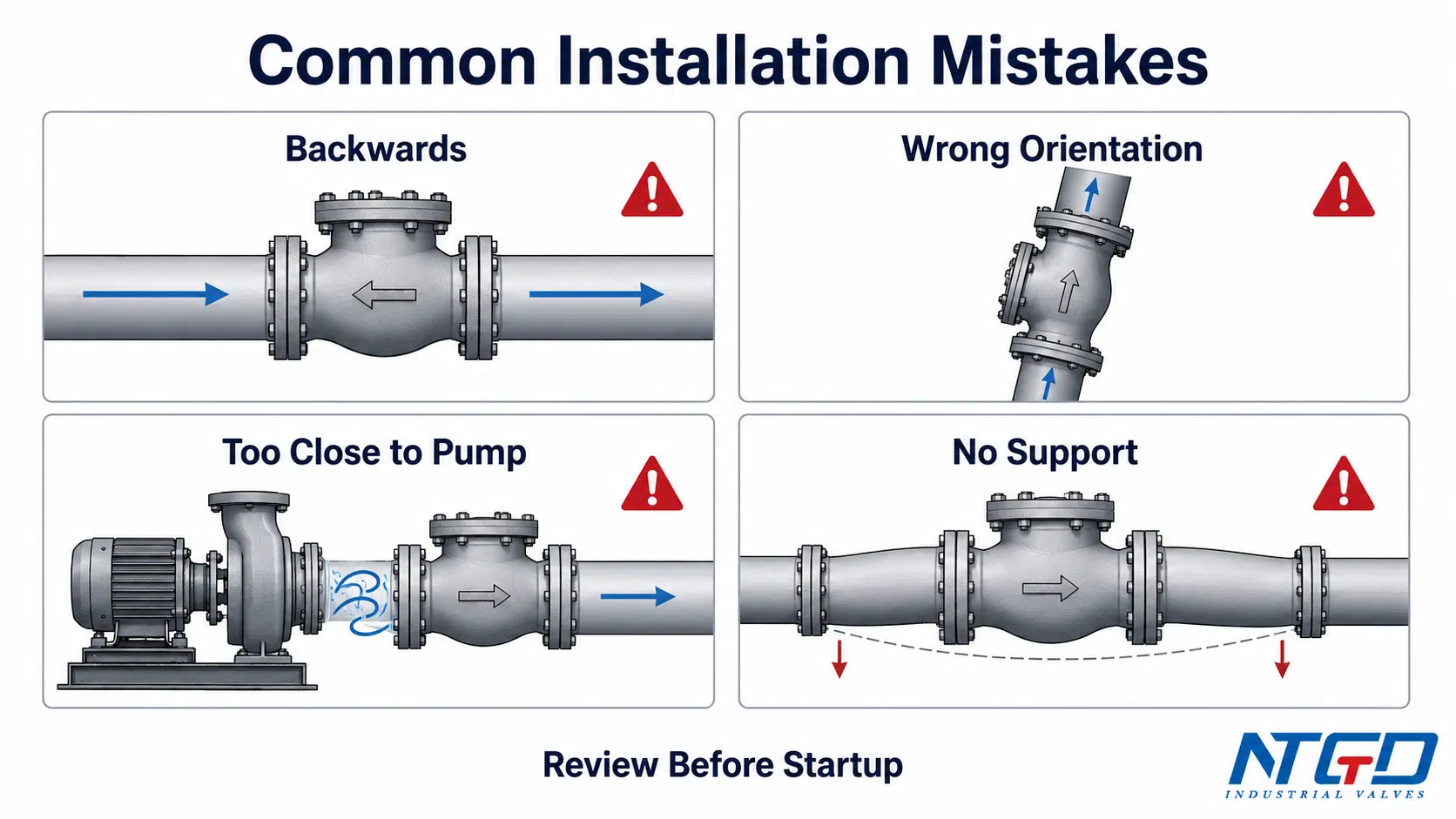
Even experienced technicians make these errors. Knowing them helps you prevent failures.
• Ignoring the flow arrow: the leading cause of valve failure
• Over-tightening bolts or threads: cracks the body or distorts the seal
• Skipping pipe cleaning: debris causes seat damage and premature wear
• Mixing horizontal and vertical use: not all valves are universal
• Using the wrong gasket or sealant: chemical incompatibility leads to leaks
Frequently Asked Questions About Ball Check Valve Installation
What happens if a ball check valve is installed backward?
A backward installation prevents the ball from lifting during forward flow, which blocks the line entirely. It also eliminates backflow protection and can cause water hammer, seat damage, or catastrophic failure under pressure.
Can a ball check valve be installed vertically?
Only valves specifically rated for vertical service should be installed in upright positions. For upward flow, the inlet goes at the bottom. Downward flow requires a spring-assist mechanism. Horizontal valves placed in vertical lines often fail to seal properly.
How tight should flange bolts be on a check valve?
Bolts should be tightened evenly in a crisscross pattern to distribute pressure uniformly. Always follow the manufacturer’s torque specifications. Uneven tightening warps the valve body and creates leaks.
Why is pipeline cleaning important before installing a check valve?
Debris, rust, or scale can damage the sealing surface or prevent the ball from seating fully. A contaminated seat leads to leaks and premature wear. Flushing the line ensures optimal sealing performance and extends valve life.
How do I know if my ball check valve is failing after installation?
Common signs include gradual leakage at joints, incomplete closure allowing backflow, excessive noise during operation, and increased pressure drop across the valve. Chattering or banging sounds also indicate installation or sizing issues.
What standards apply to ball check valve installation?
Relevant standards include local plumbing codes, ASME B31.1 and B31.3 for power and process piping, and sanitary standards like FDA, 3-A, or EHEDG for food and pharmaceutical systems. Always follow the manufacturer’s specific guidelines as well.
Key Takeaways for a Successful Ball Check Valve Installation
Proper ball check valve installation comes down to three essentials: cleanliness, correct orientation, and verified performance. Always align the flow arrow with system direction, choose the right mounting method for your application, and test thoroughly before full operation. These steps prevent backflow, extend valve life, and protect your entire system from avoidable failures.
Before starting your next project, review the manufacturer’s manual for model-specific details. Skipping pre-installation checks or post-installation tests invites costly downtime. With careful attention to each phase, your ball check valve will deliver reliable, trouble-free service for years.