
Installing a water well pump is a critical task that ensures your home or property has reliable access to clean water. If you’re wondering how to wire a water well pump, the process involves more than just connecting wires. It requires understanding electrical codes, selecting the right components, and ensuring long-term durability. Whether you’re replacing an old pump or setting up a new well system, proper wiring is essential for safety, efficiency, and compliance with the National Electrical Code.
This guide walks you through every step, from conductor selection and splice sealing to pressure switch setup and final testing. You’ll learn how to choose between 2-wire and 3-wire systems, size breakers correctly, install subpanels for future flexibility, and avoid costly mistakes that could leave you without water.
Choose the Right Pump Wiring Configuration
The first decision in wiring a water well pump is determining whether your system uses a 2-wire or 3-wire configuration. This choice affects everything from cable type to required hardware, so select carefully before purchasing materials.
2-Wire vs 3-Wire Systems
A 2-wire pump has two hot conductors (typically black and red) plus a ground wire. It contains an internal start switch and capacitor, eliminating the need for an external control box. These are common in residential setups with pumps up to 1 HP, such as a 3/4 HP submersible unit using 12 AWG cable.
In contrast, a 3-wire pump uses three wires (usually black, red, and yellow) plus ground. It requires an external control box to manage starting torque via a potential relay and dual capacitors. This setup is better suited for higher-horsepower motors (1.5 HP or more) or long wire runs where voltage drop is a concern.
If your existing system has no control box and uses only two hot wires, you’re working with a 2-wire configuration. This simplifies installation and reduces the number of components needed.
Match Control Box to Pump Specifications
For 3-wire pumps, the control box must match the motor’s specifications exactly. Terminals are labeled L1 and L2 for line input, with B (Black), R (Red), and Y (Yellow) connecting directly to the pump leads. The box houses the start capacitor, run capacitor, and potential relay, which work together to deliver high starting current before disconnecting once the motor reaches speed.
Mount the control box near the pressure switch or power source for short, efficient connections. Always follow manufacturer labeling and never interchange wires between different pump models.
Size Conductors and Conduit Properly
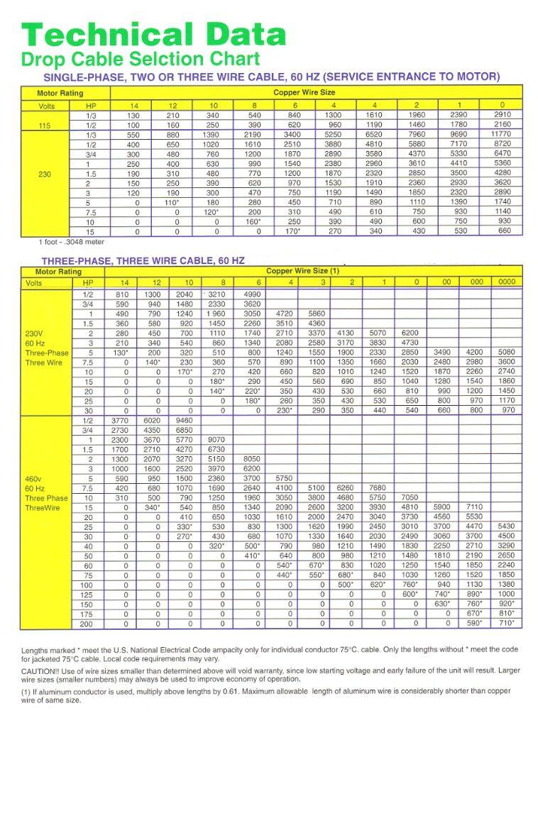
Using the correct wire gauge and conduit protects against overheating, voltage drop, and code violations. Incorrect sizing is one of the most common causes of premature pump failure.
Choose the Correct Wire Gauge
Select wire gauge based on pump horsepower and circuit length. For 1/2 to 3/4 HP pumps under 100 feet, 14 AWG works for short runs. A 1 HP pump up to 150 feet typically uses 12 AWG. For 1 to 1.5 HP pumps exceeding 150 feet, upgrade to 10 AWG to limit voltage drop. Motors at 2 HP or higher with long runs require 8 AWG or larger.
Even if the motor’s full load amps allow smaller wire, upgrade to #10 AWG for runs over 150 feet to keep voltage drop under the NEC-recommended 5% (12V on 240V). A 1 HP pump drawing 8 to 10 amps can use a 15A breaker and #12 AWG wire up to 150 feet. Beyond that, step up to #10 AWG.
Install 1″ PVC Conduit Correctly
Run a continuous 1″ Schedule 40 PVC conduit from your main panel or subpanel to the pump house, buried 24 inches deep and bedded in sand. This protects against physical damage and allows easy future upgrades.
Inside the conduit, use individual THWN-2 or THHN conductors, not UF cable. While UF can be used above ground, it’s not suitable for full conduit pulls due to fill and bend restrictions. If running conduit the entire way, pull individual THWN wires, not pre-sheathed cable.
Pull Four Wires for Future Flexibility
Even if your pump only needs two hots and a ground, pull four THWN-2 conductors. Use two #10 AWG black wires for hots, one #10 AWG white for neutral, and one #10 AWG green for ground. This allows you to install a 30A subpanel at the pump house later for lighting, GFCI outlets, or heat tape without digging again.
Seal Underwater Splices Securely
The connection between the drop cable and pump leads happens below water level, so it must be watertight and mechanically strong to prevent corrosion and failure.
Crimp and Heat-Shrink Each Conductor
Before lowering the pump, strip one-half inch of insulation using a proper wire stripper. Slide dual-wall heat shrink tubing onto each wire before crimping. Use metal crimp connectors (non-insulated) for maximum strength. Crimp firmly with a professional tool or vice grips. Apply heat with a torch or heat gun to seal the tubing, melting the inner adhesive layer for a waterproof bond. These sealed splices are designed for permanent submersion when done correctly.
Use Manufacturer-Approved Splice Kits
Opt for pre-packaged splice kits designed for submersible pumps. They include dielectric grease or sealant, pre-insulated crimps, waterproof sleeves, and strain relief clamps. Match the kit to your cable type and pump model. Never use standard wire nuts underwater because they will fail.
Wire the Pressure Switch Correctly
The pressure switch controls when the pump turns on and off based on system pressure, typically at 30/50 psi or 40/60 psi settings. Proper wiring ensures reliable operation and prevents short cycling.
Identify Terminal Layout
Remove the cover to reveal the terminal configuration. Two outer terminals serve as line input from the breaker or disconnect. Two inner terminals provide load output to the pump or control box. Two grounding bolts are located at the bottom. Always pair the switch with a pressure tank to reduce cycling and extend pump life.
Connect Wires with Clockwise Hooks
Cut feed wire to length and strip three-fourths inch of insulation. Bend the end into a clockwise hook to wrap under terminal screws. Tighten securely but avoid overtightening, which can damage terminals. Use wire nuts (size 2S) if splicing, positioning them open-end up to avoid moisture pooling. Wrap connections with Scotch Super 33+ tape for added moisture resistance, and seal conduit entries with dielectric grease or silicone.
When joining stranded and solid wires, lead with the stranded wire slightly ahead to ensure full contact and prevent overheating.
Power Input Options
You can supply power in two ways. Run a dedicated 240V circuit with a double-pole breaker directly from the breaker box. Alternatively, use a NEMA L-30 plug for temporary setups by cutting off the neutral wire (not used), connecting two hots and ground. This method works well for testing pumps up to 2 HP.
Install Control Box for 3-Wire Pumps
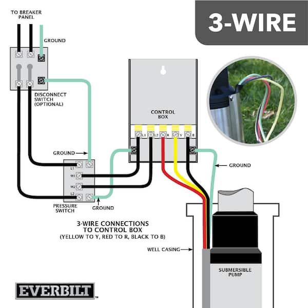
If you’re using a 3-wire pump, the control box is essential for safe startup and motor protection.
Label and Connect Terminals
Terminals are clearly marked for easy identification. Connect L1 and L2 to line input from the pressure switch. Match R (Red), Y (Yellow), and B (Black) to the corresponding pump wire colors. Connect the ground terminal to the green or bare wire. Open the box, connect each wire to its matching terminal, and tighten securely. Ensure all insulation is intact and no bare wire extends beyond the screw.
The control box provides extra starting torque via a start capacitor and potential relay, which is critical for larger motors or deep wells.
Size Breaker and Provide Disconnect
Electrical safety starts with proper overcurrent protection and a code-compliant disconnect.
Select Correct Circuit Breaker
Use a double-pole breaker sized to the pump’s full load amps. For 1 HP or less, use 15 to 20A. For 1.5 to 2 HP, use 20 to 30A. Always check the nameplate on the pump because it specifies minimum and maximum breaker sizes. Never guess. A 1 HP pump typically uses a 15A breaker with #12 AWG wire.
Add GFCI Protection for Safety
While not always required by code, GFCI protection is highly recommended, especially outdoors or in damp locations. Options include a GFCI breaker in the main panel (best for permanent installs) or a weatherproof GFCI outlet near the wellhead. For temporary testing, powering the pump via a remote GFCI outlet 25 feet away is acceptable, but upgrade to a local disconnect for permanent use.
Install a Subpanel at the Pump House

Adding a small subpanel at the pump house increases functionality and meets code for detached structures.
Build a 30A Subpanel Setup
Install a 4- or 6-space subpanel fed by a 30A double-pole breaker in the main panel. Use #10 AWG x4 conductors (two hots, neutral, ground) pulled through your 1″ conduit. Inside the subpanel, install a 15A double-pole breaker for the pump using #12 AWG wire. Add a 15A single-pole GFCI breaker for 120V circuits (lights, outlets, heat tape). Leave one spare slot for future use.
Separate Neutral and Ground Bars
In any subpanel, neutrals and grounds must be isolated. Remove the bonding screw or strap. Install an add-on ground bar if needed. Neutrals go only to the neutral bar, and grounds connect only to the ground bar. Failure to separate them creates a dangerous parallel path for current.
Drive Ground Rods at Pump House
If the pump house is a detached structure, you must install grounding electrodes. Drive one 8-foot copper-clad steel rod vertically nearby. Connect with #6 AWG bare copper wire from subpanel ground bar to the rod. In rocky soil, use two 4-foot rods spaced at least 6 feet apart.
No ground rod is needed if using only an A/C disconnect. However, if a subpanel is installed, ground rods are mandatory regardless of disconnect type.
Follow the Complete Wiring Path
Understanding the complete electrical path ensures nothing is missed during installation.
Map the Circuit Flow
The correct sequence flows from the main panel through a 240V double-pole breaker to 1″ PVC conduit with #10 AWG x4 THWN-2 wires. From there, power goes to an optional subpanel, then to a 15A 2P pump breaker using #12 AWG to the pressure switch. For 3-wire systems, the path continues through the control box (L1/L2 to R/Y/B) to the submersible pump via sealed splice, with continuous grounding throughout.
For temporary setups, use this path: GFCI outlet to extension cord to pressure switch to pump. Use this only for testing, never as a permanent solution.
Test Before Finalizing
Never energize the system without a full pre-checklist to avoid damage or safety hazards.
Verify All Connections
Before turning on power, confirm all wire terminations are tight and insulated. Double-check L1 to L1, L2 to L2, and ground continuity. Inspect heat-shrink seals for gaps or bubbles. Reinstall the well cap securely with four 11 mm bolts. Pre-charge the pressure tank to 2 psi below cut-in pressure (28 psi for a 30/50 switch).
Energize and Monitor
Restore power at the breaker and let pressure drop. The switch should click and pump engage within seconds. Watch for water flow and rising gauge pressure. Listen for abnormal noise or vibration, and confirm no breaker trips. If the breaker trips immediately, suspect a short circuit or ground fault. Turn off and inspect all connections.
Maintain for Longevity
Proper maintenance extends pump life and prevents unexpected outages.
Annual Inspection Tasks
Each year, test pressure switch operation, check tank air charge with a tire gauge, inspect wire connections for corrosion, and clean debris from around enclosures.
Every 5 to 10 Years
Pull the pump for inspection, especially in sandy or mineral-heavy water. Replace the torque arrester and inline check valve if worn. Verify cable integrity and splice condition. Typical submersible pump lifespan is 8 to 15 years, depending on water quality, cycle frequency, and installation quality.
Follow NEC Requirements and Safety Practices
Key code sections apply to well pump installations. Article 680.9 covers submersible pump installations. Article 430 addresses motor circuits. Article 250 handles grounding, and Article 300 covers wiring methods. All splices must be either accessible or approved for submersion. Label disconnects clearly with “WELL PUMP DISCONNECT.”
Protect against environmental damage by burying lines below frost depth. Use black corrugated conduit to shield against rodents. Install weatherproof enclosures for switches and controls. Add heat tape with GFCI in cold climates, and insulate pipes with snap-on sleeves.
Essential tools include wire strippers, a crimp tool, a heat gun, adjustable and pipe wrenches, fish tape, a multimeter, and a non-contact voltage tester.
Frequently Asked Questions About Wiring a Water Well Pump
Can I install a well pump on a 120V circuit?
No. Residential submersible well pumps require 240V single-phase power. Attempting to run a pump designed for 240V on 120V will cause the motor to stall, overheat, and fail prematurely.
What happens if I use the wrong wire gauge?
Using wire that’s too small causes excessive voltage drop, which leads to reduced pump performance, increased energy consumption, and premature motor failure. The NEC recommends keeping voltage drop under 5% for optimal performance.
Do I need a permit to wire a well pump?
Electrical work typically requires permits and inspections in most jurisdictions. Always check local codes before starting the project. Professional installation may be required in some areas.
How deep should the electrical conduit be buried?
Burial depth of 24 inches is standard for residential circuits, but local frost depth requirements may mandate deeper burial. Check with your local building department for specific requirements in your area.
Can I use an extension cord for a permanent well pump installation?
No. Extension cords are for temporary use only. Permanent installations require dedicated circuits with proper conduit protection, appropriate wire gauges, and code-compliant connections.
Key Takeaways for Wiring Your Water Well Pump
Wiring a water well pump correctly ensures years of reliable service. Select the right wiring configuration (2-wire vs 3-wire) based on your pump’s horsepower and installation requirements. Use proper wire gauge (typically #12 AWG for most residential pumps up to 150 feet) and install conduit to protect the wiring. Seal all underwater splices with heat-shrink crimp connections to prevent moisture ingress. Install GFCI protection for safety, and follow NEC codes throughout the process. Whether you’re doing a DIY install or verifying a contractor’s work, this guide gives you everything you need to get it right and keep your water supply flowing reliably.