A failing backflow valve can silently contaminate your clean water supply, putting health at risk and violating plumbing codes. Backflow happens when pressure changes reverse water flow, pulling pollutants from irrigation systems, boilers, or industrial equipment into drinking water. The U.S. Environmental Protection Agency tracks over 10,000 backflow incidents each year, some involving toxic chemicals or medical waste. Learning how to check backflow valve assemblies correctly protects your household and keeps you compliant with local regulations.
Annual testing is mandatory for all backflow devices, whether on a residential sprinkler system or commercial fire line. Even newly installed or repaired units must pass inspection before use. While some homeowners try DIY checks, accurate results require certified professionals with calibrated tools and proper training. This guide walks you through the entire process, covering device types, testing procedures, failure signs, and compliance steps. You will learn exactly what technicians do during an inspection and what to watch for between annual tests.
Identify Your Backflow Device Type
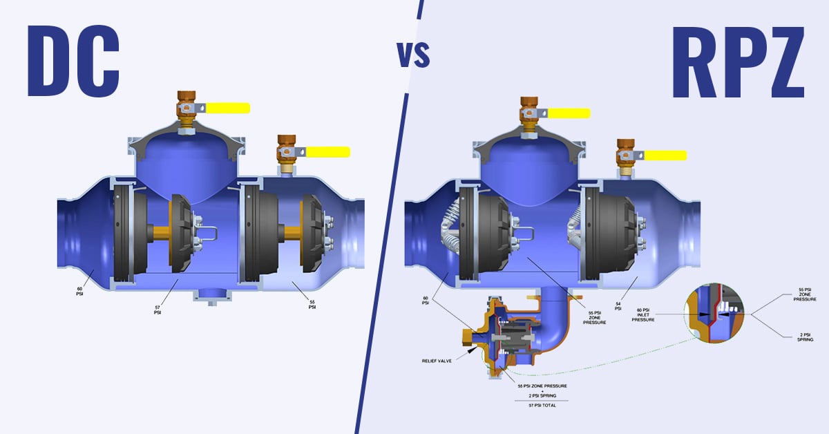
Know the Difference Between RPZ and DCV Assemblies
Backflow preventers come in different designs, each suited for specific hazard levels. The two most common types are Reduced Pressure Zone (RPZ or RP) assemblies and Double Check Valve (DCV) assemblies. Each has distinct applications, components, and testing methods that affect how you check them.
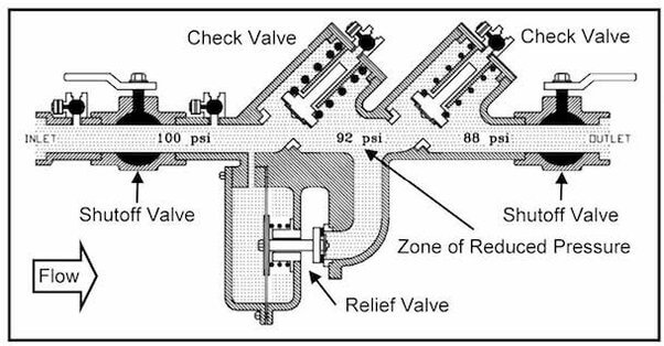
RPZ valves protect high-hazard systems like commercial kitchens, medical facilities, and fire suppression lines where contamination could be life-threatening. They include two check valves and a relief valve that discharges water if pressure drops between the checks, providing fail-safe protection.
DCV assemblies work in lower-risk settings such as residential irrigation systems. They contain two check valves but lack a relief valve, relying solely on dual redundancy for protection. Because they do not vent, they are not suitable for toxic hazards.
Locate Key Identification Markers on the Device
Confirming your device type is the first step in knowing how to check backflow valve assemblies properly. Look for these markers:
- Flow arrows on the body showing water direction
- Labels like “ASSE 1013” (standard for RPZ) or model numbers such as Watts 007 M1 QT
- Test cocks, which are four small threaded ports on RPZ units and three on DCVs
If no label exists, count the test ports. RPZ devices always have four test cocks numbered 1 through 4, while DCVs typically have three. Matching these features ensures you apply the correct testing protocol.
Gather Required Testing Equipment
Use Professional-Grade Test Kits
Checking a backflow valve accurately requires specialized tools that consumer-grade kits often lack. Certified technicians use calibrated test kits such as:
- Watts TK9A, TK-7, or TK-99D Delta Lite
- Krueger Instruments TK2
- Wilkins TG5
These kits include analog or digital gauges measuring 0 to 15 psi differential with ±0.2 psi accuracy. For RPZ testing, a three-hose configuration covering high, low, and vent functions is required under the USC 10th Edition code.
Hoses follow a color coding system: red for high pressure, blue for low pressure, and yellow for vent or bypass. Always verify calibration dates, since gauges must be recalibrated annually to maintain accuracy.
Prepare Essential Accessories for the Job
Beyond the main kit, technicians carry several supporting items:
- Threaded test cock adapters with rubber O-rings
- Teflon tape for sealing connections
- Channel locks and screwdrivers
- Buckets or drain hoses for runoff
- Zip ties for securing discharge lines
Adapters are crucial because older devices may have non-standard threads. A full adapter set allows retrofitting obsolete fittings. Keep all tools clean and organized to avoid cross-contamination or misreads during the test.
Conduct Pre-Test Safety Checks
Notify Occupants and Isolate the System
Before starting, inform building occupants that water will be temporarily shut off. Never test if uninterrupted supply is critical, such as in hospitals or labs, unless a bypass system is in place.
Turn off all pumps connected to the domestic water line. This prevents pressure surges during isolation that could damage gauges or valves.
Perform a Visual Inspection of the Site
Inspect the device and surrounding area for red flags before testing:
- Unauthorized connections upstream, like a hose bib before the preventer
- Corrosion or cracks on copper piping
- Cement damage or moisture exposure on underground lines
- Missing sleeves on irrigation pipes buried in soil
Ensure the main shut-off and zone valves are clearly labeled with waterproof tags. Unlabeled valves increase error risk during emergencies or future maintenance work.
Flush Test Cocks and Install Adapters
Open test cocks in sequence: 4, 3, 2, then 1. Let water run briefly to flush debris. Close them in reverse order: 1, 2, 3, 4.
Attach adapters to each test cock, threading them in the direction of flow. Hand-tighten only, since over-torquing damages O-rings. Confirm seals are intact and leak-free before connecting hoses.
Test Double Check Valve (DCV) Assembly
Set Up the Single-Hose Method
For DCV testing, use the single-hose method. Connect the high-pressure hose (red) to Test Port 3. Open Port 3, then open both valves (A and B) on the test kit to purge air.
Close Valve B. The gauge should read full line pressure, often around 73 PSI. A stable reading confirms system integrity and no hose leaks.
Isolate Upstream and Check Valve 1
Close Shut-off Valve 1 (upstream) completely. Open Valve B to reduce pressure to exactly 2 PSID. Re-bleed air using Valves A and B.
Hold this pressure. If it rises, Shut-off Valve 1 is leaking, which means automatic failure.
Now open Test Port 2. Observe the gauge: pressure must not drop below 1 PSID. A stable 2 PSID reading means Check Valve 1 is sealing properly.
Close Port 2 and 3. Reopen Shut-off Valve 1 to restore flow.
Test Check Valve 2 for Proper Sealing
Move the high-pressure hose to Test Port 4 (downstream). Open Port 4 and purge air.
Close Shut-off Valve 1 again. Reduce pressure to 2 PSID. If pressure rises, Shut-off Valve 1 is faulty and the test fails.
Open Test Port 3. The needle may dip slightly but must remain above 1 PSID. This confirms Check Valve 2 is intact.
Close all ports, remove equipment, and restore the system to normal operation.
Test Reduced Pressure Zone (RPZ) Assembly
Configure the Three-Hose Setup
RPZ testing requires a three-hose kit with specific connections:
- Red hose connects to Test Cock 2 (high pressure)
- Blue hose connects to Test Cock 3 (low pressure)
- Yellow hose connects to Test Cock 4 (bypass or vent)
Close both shut-off valves. If a bypass line exists, open it to maintain water flow to the building during testing.
Purge Air and Record Static Pressure
Open Test Cock 1 (inlet) and the high-pressure valve to flush air. Open Test Cock 3 to bleed the low side. Reopen the high valve to purge the bypass line.
Close the downstream shut-off (Shut-off 2) while water flows. Close bleed valves.
Record static line pressure, which is often around 45 PSI. Some gauges read descending scales, so accuracy improves when the needle moves downward.
Test the Relief Valve Opening Point
Loop the yellow (vent) hose to the gauge’s designated side. Slowly open the high-pressure valve to increase pressure on the relief valve.
Watch closely. At the first drip, stop increasing pressure.
Pass: Relief valve opens at or above 2.0 PSID
Fail: Opens below 2.0 PSID or does not open at all
Under USC 10th Edition, only the opening point is recorded. Full discharge is not required.
Check Valve 2 Back Pressure Tightness
Close Test Cock 4 and the high-pressure valve. Reconnect the high side to Test Cock 2.
Open the low-pressure valve to build pressure. Monitor the gauge.
Pass: Pressure stabilizes (often around 7.0 PSI) and the valve holds
Fail: Pressure drops, indicating a leak
Under USC 10th Edition, record as “Closed Tight” or “NA.” No differential value is needed for this step.
Check Valve 1 Differential Pressure
Reset the gauge by opening and closing the low bleed valve. Open the high bleed valve.
The gauge drops to a stable differential reading, often around 7.6 PSI.
Pass: Reading is ≥ 5.0 PSID
Fail: Reading falls below 5.0 PSID
Avoid parallax error by reading analog gauges straight-on rather than from an angle.
Troubleshoot Common Test Failures
Diagnose Shut-Off Valve Leaks
If pressure rises during isolation, Shut-off Valve 1 is leaking. Debris or worn seals prevent full closure. This causes automatic failure, so repair or replacement is needed before retesting.
Never assume the backflow device itself is faulty without ruling out upstream valve issues first.
Address Relief Valve Problems
An early-opening relief valve (below 2.0 PSID) points to compromised internal springs or seals. A valve that will not open suggests blockage or mechanical failure.
Both conditions require immediate disassembly, cleaning, or replacement of the affected components.
Detect Fouled Check Valves
Check valves fail due to sediment buildup, aging seals, or mineral deposits. If differential pressure is too low (below 5 PSID) or back pressure leaks appear, inspect internal discs and seats.
Clean or replace components per manufacturer specifications. Never reuse old O-rings on reassembly.
Resolve Water Flow from the Relief Valve
If water continuously drips from the relief discharge during normal operation (not during testing), Check Valve 1 is likely fouled. This allows pressure to build in the zone, triggering the relief valve.
Shut down the system and schedule servicing immediately to prevent contamination risks.
Overcome Installation Obstacles
Fix Space Constraints Around the Device
Tight spaces, especially with copper piping close to the device, can block hose access during testing.
Solution: Install a 90° elbow with a new shut-off valve and threaded adapter to create clearance. This modification must comply with local plumbing code.
Adapt Non-Standard Fittings
Older or rare brands may have unusual test cock threads that standard kits cannot connect to.
Solution: Carry a full adapter kit. Retrofit older units with modern, code-compliant test ports when possible to ensure future testability.
Manage Drainage Challenges During Testing
RPZ testing releases water via the relief valve. Without a floor drain nearby, runoff can cause slips or property damage.
Solution: Use a bucket or direct flow through a hose to an approved drainage point. Secure lines with zip ties to prevent splashing during the test.
Complete Post-Test Compliance Steps
Document All Readings Accurately
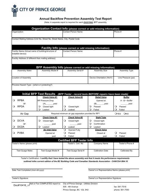
After testing, fill out the official form with precision:
- Record static pressure
- Note differential readings
- Document relief valve opening point
- Mark “NA” for non-required tests, such as shut-off leakage under USC 10th Edition
This report goes to your local water authority, so accuracy matters for compliance.
Issue Certification or Repair Notice
If the device passes, take these steps:
- Attach a certification tag to the assembly
- Submit the test report to the local water utility
- Provide a copy to the property owner
If it fails, specify the exact failure (for example, “Relief valve opened at 1.5 PSID”), recommend repair or replacement, and schedule a follow-up test after correction.
Recommend Preventive Maintenance
Extend device life with these actions:
- Replace worn O-rings and seals immediately
- Ensure underground lines are sleeved to prevent moisture damage
- Reapply waterproof labels if they have faded
- Schedule annual inspections without delay
Recognize Pass/Fail Criteria at a Glance
| Component | Test | Pass Standard | Failure Sign |
|---|---|---|---|
| Shut-off Valve | Pressure Stability | Holds 2 PSID | Rises during test |
| Check Valve 1 | Differential Pressure | ≥ 5.0 PSID | Below 5.0 PSID |
| Check Valve 2 | Back Pressure Hold | “Closed Tight” | Pressure drop |
| Relief Valve (RPZ) | Opening Point | ≥ 2.0 PSID | Opens early or not at all |
| Visual Inspection | Physical Condition | No damage, proper labeling | Cracks, corrosion, missing sleeves |
Note: Local codes may vary slightly, but 2.0 PSID for the relief valve and 5.0 PSID for the check valve are universal benchmarks across most jurisdictions.
Frequently Asked Questions About Checking Backflow Valves
How Often Should a Backflow Valve Be Tested?
Backflow valves require annual testing in most jurisdictions. Testing is also mandatory after initial installation, relocation, repair, or whenever debris accumulation or valve misalignment is suspected. Skipping these required tests can result in code violations and contaminated water risks.
Can a Homeowner Test a Backflow Valve Without Certification?
In most U.S. metropolitan areas, only licensed plumbers or technicians with specific backflow certification can perform official testing. DIY checks lack the calibrated equipment and legal standing needed to submit results to local water authorities. Homeowners can perform visual inspections between annual tests but cannot certify compliance themselves.
What Happens If a Backflow Valve Fails the Test?
If a backflow valve fails, immediate repair or replacement is required to maintain system safety. The technician provides a detailed report citing the specific failure, such as a relief valve opening below 2.0 PSID or check valve differential below 5.0 PSID. A follow-up test is scheduled after corrections are made.
What Is the Difference Between RPZ and DCV Backflow Preventers?
RPZ (Reduced Pressure Zone) assemblies are used in high-hazard environments like medical facilities and fire suppression systems. They include a relief valve that discharges water during pressure drops. DCV (Double Check Valve) assemblies are used in lower-risk settings like residential irrigation and rely on dual check valves without a relief valve.
How Long Does a Backflow Valve Test Take?
A standard backflow valve test typically takes 30 minutes to one hour, depending on the device type and site conditions. RPZ assemblies take longer due to their three-hose configuration and multiple test points. Complex installations with space constraints or drainage issues may require additional time.
What Are the Signs of a Failing Backflow Valve Between Tests?
Common warning signs include continuous water dripping from the relief valve discharge, reduced water pressure throughout the building, visible corrosion or cracks on the device, and unexplained water discoloration. If you notice any of these signs, schedule an inspection before the next annual test date.
Key Takeaways for Checking Your Backflow Valve Safely
Knowing how to check backflow valve assemblies protects both your health and your compliance standing. The two main device types (RPZ and DCV) require different testing methods but share universal pass benchmarks of 2.0 PSID for relief valves and 5.0 PSID for check valves. Always hire a certified technician with calibrated equipment for official testing, since DIY results will not satisfy local water authorities.
Schedule your next annual inspection now if you cannot remember the last test date. Keep records of all certifications and repair reports in an accessible file. If you spot water dripping from the relief valve or notice reduced pressure, do not wait for the scheduled test. Contact a licensed backflow specialist today to ensure your water supply stays clean and your property remains code-compliant.