Reading a hydraulic schematic and spotting a check valve with a dashed line attached means you have found a pilot check valve symbol. This component controls fluid flow under pressure and can be remotely opened using an external pilot signal. Unlike basic check valves that only block reverse flow, pilot-operated versions give you command over both directions when needed. Mastering this symbol is essential for diagnosing circuits, designing systems, and ensuring safe load-holding operations.
This guide breaks down every variation of the pilot check valve symbol, explains how each one functions in real-world applications, and highlights common pitfalls in circuit design. You will learn how to distinguish between pilot-to-open and pilot-to-close configurations, interpret area ratios, recognize external drain lines, and avoid dangerous misapplications like using PO checks for overrunning loads.
Standard Check Valve Symbol Basics
Before exploring pilot variants, you need a solid grasp of the foundation: the standard check valve symbol.
One-Way Flow Design
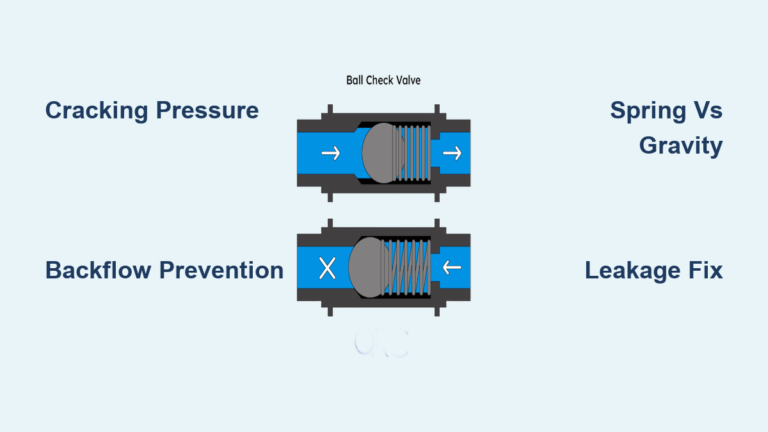
The basic check valve symbol shows a circle (ball or poppet) resting against a V-shaped seat. Flow is allowed from the inlet (typically the bottom) to the outlet (top), but blocked in reverse. No spring appears in the symbol unless required for operation.
- No Spring: Relies on gravity or flow stoppage to close. Common in vertical inline installations.
- With Spring: A zig-zag line indicates a spring-loaded poppet. The valve opens only when inlet pressure exceeds spring force.
- Labeling Practice: Engineers often write the crack pressure (like “5 psi”) next to the symbol for clarity.
Ball vs. Guided Poppet Types
- Ball Check Valves: Simple and common, but wear creates grooves on the seat. During reassembly, the ball must return to the same rotational position or leakage occurs.
- Guided Poppet Valves: Use a machined guide to ensure perfect reseating. Ideal for maintenance-heavy systems where alignment cannot be guaranteed.
Inline vs. Right-Angle Bodies
- Inline: Flow pushes the poppet straight ahead. The body has side ports above the seat for fluid passage.
- Right-Angle: Fluid turns 90 degrees around the poppet, reducing flow restriction.
- Maintenance Tip: Prefer right-angle or cartridge-style valves. They are easier to service without disconnecting plumbing.
Pilot-to-Open Check Valve Symbol
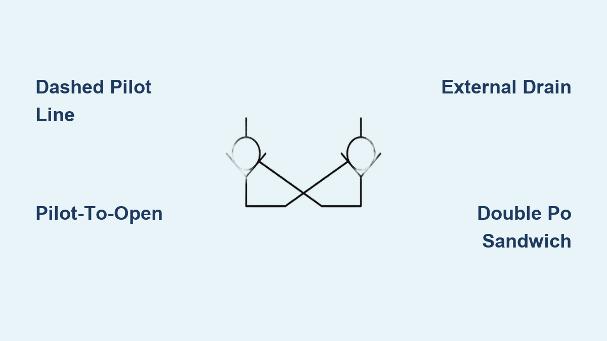
This is the most common type of pilot check valve symbol and a staple in load-holding circuits.
Identifying the Symbol
Look for these key elements:
- The standard ball-on-seat check valve
- A dashed pilot line connected to the side or bottom
- Optional dot at intersection points indicating a physical connection
✅ Key Identifier: The dashed line represents a control signal, usually hydraulic pressure, that forces the valve open.
How It Works
- Unpressurized Pilot: Acts as a standard check valve. Flow allowed in one direction, blocked in reverse.
- Pressurized Pilot: Pilot pressure lifts the poppet via a piston, allowing reverse flow even under backpressure.
Area Ratio and Force Dynamics
The ability to open against high pressure depends on mechanical advantage:
| Ratio | Function |
|---|---|
| 3:1 to 4:1 | Standard ratio common in most industrial valves |
| Up to 100:1 | High-ratio design using low pilot pressure to open against extreme backpressure |
- Example: With a 4:1 ratio, 100 psi pilot pressure can overcome 400 psi backpressure.
- This ratio appears in the valve’s technical specs, not the symbol itself.
Decompression Sub-Poppet Design
Some symbols include a small inner poppet within the main one.
- Purpose: Allows a small flow path to open first, bleeding off trapped pressure before full poppet lift.
- Limitation: Only effective for trapped volume decompression, not load-induced pressure.
⚠️ Warning: Never rely on decompression features for safety in load-support applications.
External Drain Line in Pilot Check Symbols
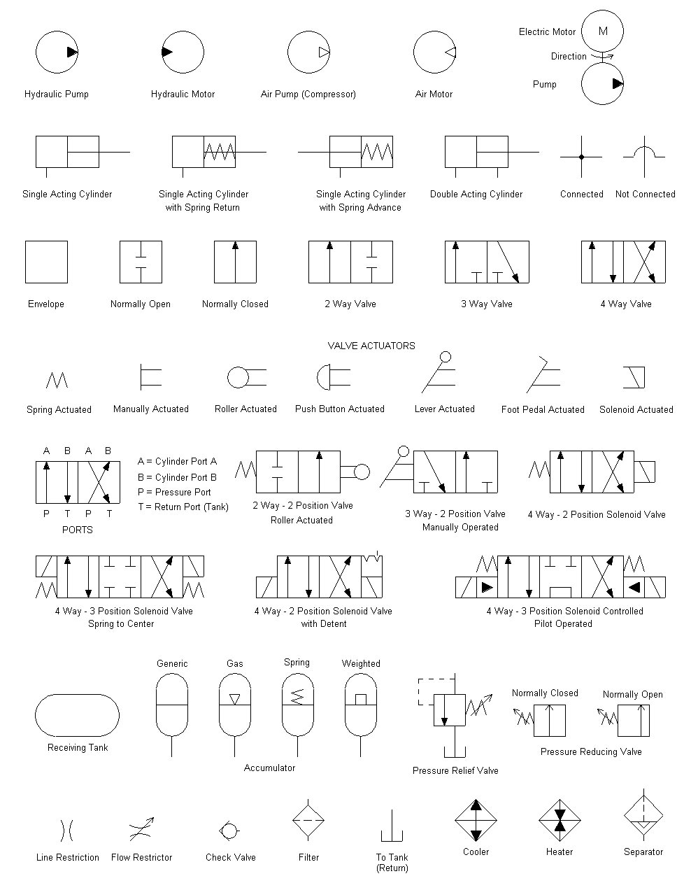
Not all pilot-to-open valves work the same way. Some require an external drain.
Why Internal Drain Fails
In standard designs, pressure from the free-flow port acts on the stem side of the pilot piston, resisting the pilot signal.
- If downstream components like flow controls or counterbalance valves create backpressure, the pilot may not generate enough force to open the valve.
External Drain Solution
An additional line (often labeled “X” or “D”) vents the pilot piston’s stem side to tank.
- Symbol Clue: A second dashed or solid line exits the pilot piston area and terminates at tank.
- Ensures pilot pressure works unopposed by backpressure.
- Also helps return the pilot piston when used in pilot-operated 2-way functions.
🔧 Pro Tip: Always verify drain line routing during installation. Plugging or blocking it causes valve failure.
Pilot-to-Close Check Valve Symbol
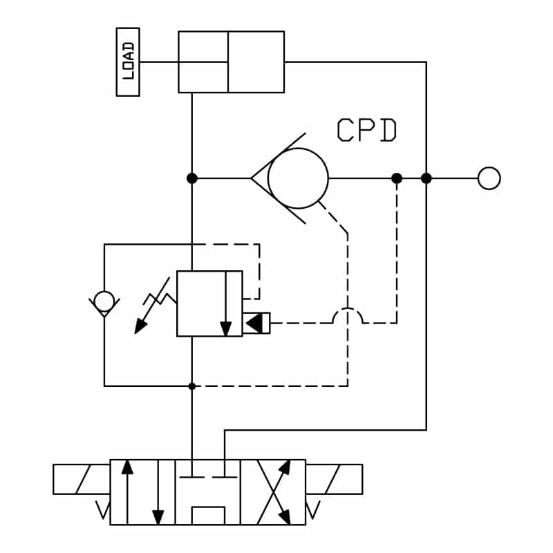
Less common but important for specific isolation tasks.
How to Recognize It
- Pilot line enters the symbol from the top, above the ball or poppet.
- Pressure applied here forces the poppet down, sealing both directions.
Operational Behavior
| State | Flow Behavior |
|---|---|
| No Pilot Pressure | Normal one-way flow |
| Pilot Pressurized | Flow blocked in both directions |
- Uses the larger surface area behind the poppet to generate closing force.
- Can seal against free flow due to area differential.
When to Use It
- Isolation circuits where complete shutoff is needed on command
- Safety interlocks that block flow regardless of direction
- Rarely used, since most applications favor shuttle valves or double PO check sandwiches
❌ Misuse Alert: Do not confuse this with pilot-to-open valves. Reversing the pilot line defeats the purpose.
Double PO Check Sandwich Plates
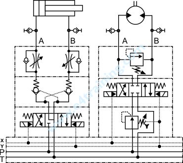
A key application in industrial valve stacks.
Symbol Representation
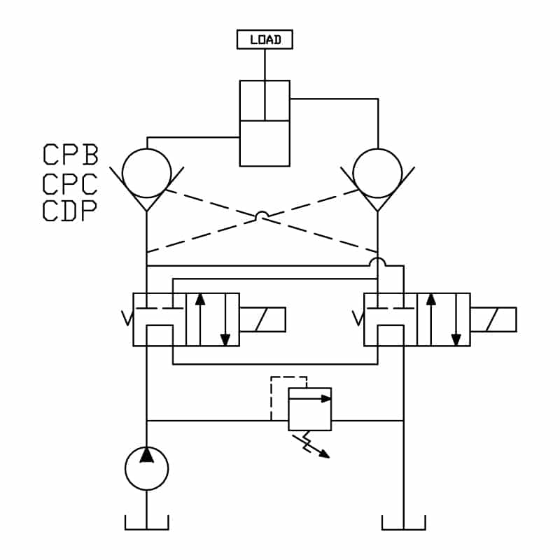
Two pilot-operated check valves drawn side-by-side or stacked, often flanking work ports A and B.
- Integrated into CETOP (ISO/D-series) directional valve manifolds.
- Positioned between the directional valve and the cylinder.
Circuit Function
| Valve State | Behavior |
|---|---|
| Directional Valve Shifted | One PO check allows forward flow; pilot signal opens the other for return |
| Neutral Position | Both PO checks close instantly, locking fluid in cylinder lines |
- Prevents cylinder drift due to spool leakage.
- Essential for vertical load holding where precision positioning is required.
Manifold Integration
- Pressure (P) and tank (T) lines run through the center.
- Work ports (A/B) connect to the cylinder.
- Pilot lines tap from P to open PO checks when actuated.
💡 Expert Note: In stack drawings, orientation matters. Valves in A/B lines may appear upside down to reflect actual flow paths.
Pilot Supply for Large Spool Valves
Big valves need help moving. This is where pilot-assisted operation comes in.
Compound Operator Symbol
For valves over D05 (NG10), the symbol shows:
- A small solenoid-operated pilot valve mounted atop the main spool
- A single pilot line feeding both stages
- An orifice symbol in the pilot line to limit flow
Why the Orifice Matters
- Main circuit may carry hundreds of GPM.
- Pilot valve handles only a few GPM.
- Orifice prevents surge damage during shifting.
⚙️ Design Rule: Always include the orifice in schematics. It is not optional in real systems.
Common Application Errors and Failures
Even with correct symbols, mistakes happen during application.
Using PO Check Valves for Runaway Loads
The Problem
- On vertical cylinders, extending too fast can cause pressure drop in the cap end.
- This reduces pilot pressure to the rod-end PO check.
- Valve shuts suddenly, causing pressure spikes and slamming motion.
The Cycle
- Cylinder extends
- Cap-end pressure drops
- Pilot signal weakens
- PO check snaps shut
- Pressure rebuilds
- Valve reopens, repeating the cycle
Result: Destructive pressure spikes, pipe fatigue, and component failure.
✅ Correct Solution: Use a counterbalance valve, not a PO check, for overrunning loads.
Extension Failure with Oversized Rods
A hidden issue in differential cylinder circuits.
Scenario
- Vertically mounted 2:1 rod-differential cylinder
- Heavy load on rod end
- PO check installed in rod line
What Happens
- To extend, pilot pressure must overcome load-induced backpressure.
- Even with a 3:1 area ratio, the system needs 300 to 400 psi to open.
- As pilot pressure builds, it also pressurizes the cap end.
- With a 2:1 ratio, 400 psi pilot pressure equals 800 psi downward force.
- More force creates higher backpressure, requiring even higher pilot pressure.
🔁 Vicious Cycle: System hits relief valve setting. Cylinder fails to extend or moves erratically.
🛠 Fix: Use counterbalance valves or pilot ratios greater than 10:1 with external pilot supply.
Fixed-Orifice Check Valves
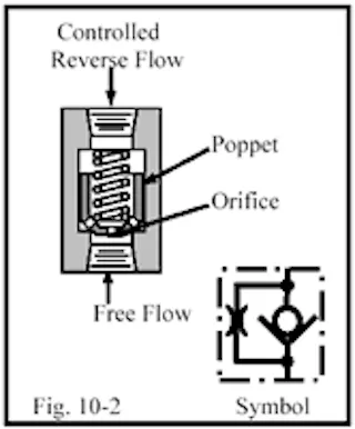
A hybrid flow control solution.
Symbol and Design
- Check valve symbol with a drilled hole through the poppet
- No adjustment mechanism, making it non-tamperable
Function
- Free flow: Unrestricted in forward direction
- Reverse flow: Limited by fixed orifice size
Applications
- Speed limiting on actuators
- Runaway protection if lines break
- Tamper-proof circuits where settings must stay fixed
🔒 Safety Best Practice: Mount directly to actuator via flange or hard pipe. Never use flexible hoses.
Related Symbols: Don’t Confuse Them
Misreading similar symbols leads to costly errors.
Shuttle Valve
- Two inlets, one outlet
- Internal ball shifts to block lower pressure
- Outputs the highest of two pressures
- Common in load-sensing circuits
❌ Not a check valve. It allows bidirectional input but single output.
Counterbalance Valve
- Designed specifically for overrunning loads
- Pre-set and sealed, do not adjust
- Includes pilot ratio and relief function
- Symbol often includes a relief valve triangle
✅ Preferred over PO check for vertical cylinders.
Flow Fuse
- Normally open
- Closes if flow exceeds set rate (such as a line burst)
- Reset by reversing flow
- Protects against uncontrolled actuator movement
⚠️ Critical for mobile equipment safety.
Reading Stack Valve Schematics
Complex circuits demand precise interpretation.
Linear vs. Stack Drawing
- Individual Valves: Location does not matter
- Stack Valves: Drawing reflects physical layering
Flow Path Logic
- Fluid enters P port and splits to all stations
- In neutral: Flows through reducing valves, then PO checks, then directional valve
- When actuated: Directional valve shifts, sending flow down through PO check and out work port
Orientation Clues
- Valves in P/T lines: Drawn upright
- Valves in A/B lines: May be inverted to show correct flow direction
🧩 Pro Insight: Trace pilot lines first. They reveal actuation logic.
Maintenance and Best Practices
Avoid downtime with smart design choices.
Choose Service-Friendly Designs
| Type | Service Difficulty |
|---|---|
| Inline Check Valves | High, requires plumbing disconnect |
| Screw-In Cartridge | Low, removable with wrench |
| Subplate-Mounted | Medium, entire subplate removed |
✅ Recommendation: Use cartridge or subplate types for easy access.
Prevent Leak-Prone Reassembly
- Ball Checks: Must be reinstalled in original rotation
- Guided Poppets: Self-align, no special handling needed
🛠 Fix: Replace worn ball checks with guided poppet versions during overhaul.
Verify Pilot Line Integrity
- Dashed lines indicate pilot signals
- Dots indicate connections
- Missing dots mean lines cross but do not connect
🔍 Troubleshooting Step: Check for kinked, blocked, or misrouted pilot lines.
Safety First: Hydraulic Energy Risks
Hydraulic systems store dangerous energy.
Critical Precautions
- Always de-energize before working
- Depressurize accumulators using proper bleed-down procedures
- Apply Lockout/Tagout (LOTO) to all energy sources
- Never assume a PO check alone is sufficient for personnel safety
⚠️ Real Risk: Stored pressure can cause sudden actuator movement or hose whip, even after shutdown.
Frequently Asked Questions About Pilot Check Valve Symbols
What does a dashed line mean on a pilot check valve symbol?
A dashed line represents a pilot signal, which is usually hydraulic pressure used to remotely control the valve. It distinguishes a pilot-operated check valve from a standard check valve and shows how the control signal connects to the poppet mechanism.
How do I tell the difference between pilot-to-open and pilot-to-close symbols?
In a pilot-to-open symbol, the dashed line connects below or beside the ball, and pressure lifts the poppet to allow reverse flow. In a pilot-to-close symbol, the dashed line enters above the ball, and pressure forces the poppet down to block flow in both directions.
What is a typical pilot area ratio for a PO check valve?
Standard pilot-operated check valves use a 3:1 to 4:1 area ratio between the pilot piston and poppet seat. High-performance designs can reach ratios up to 100:1, allowing low pilot pressure to open against very high backpressure.
Can I use a pilot check valve to hold a vertical load?
You can use one for static load holding, but never for overrunning loads. On extending vertical cylinders, pressure drops can cause the PO check to snap shut, creating dangerous pressure spikes. Use a counterbalance valve instead for overrunning load applications.
Why does my pilot check valve symbol show a second drain line?
The second line indicates an external drain that vents the pilot piston’s stem side to tank. This prevents backpressure from downstream components from resisting the pilot signal, ensuring reliable valve opening even under high system pressure.
What is the difference between a check valve and a shuttle valve symbol?
A check valve symbol shows a single ball on a seat controlling one-way flow. A shuttle valve symbol has two inlets feeding one outlet, with an internal ball that shifts to pass only the higher pressure signal. Shuttle valves are common in load-sensing circuits, not load holding.
Key Takeaways for Reading Pilot Check Valve Symbols
- The pilot check valve symbol includes a dashed line indicating remote control
- Pilot-to-open: Dashed line below or at the side, allows reverse flow when piloted
- Pilot-to-close: Line from the top, blocks flow in both directions when piloted
- External drain prevents backpressure interference, look for a second line to tank
- Double PO checks in sandwich plates lock cylinders in mid-stroke
- Never use PO checks for overrunning loads, use counterbalance valves instead
- Fixed-orifice checks provide tamper-proof speed control
- Read pilot area ratios (3:1 to 100:1) in specs, not on the symbol itself
- Maintain pilot line clarity, dots show connections while crossings do not
Mastering the pilot check valve symbol is about more than reading drawings. It is about ensuring system reliability, safety, and performance across every hydraulic application you encounter. Start by reviewing your current schematics with these distinctions in mind, and verify that pilot line routing matches your actual manifold layout.