If your pneumatic system is losing pressure, experiencing backflow, or failing under load, the wrong check valve could be the silent culprit. Pneumatic check valve types vary widely in design, response speed, and sealing capability, and choosing incorrectly can compromise efficiency, safety, and equipment life. These one-way valves are the backbone of reliable compressed air control in manufacturing, automation, and process environments.
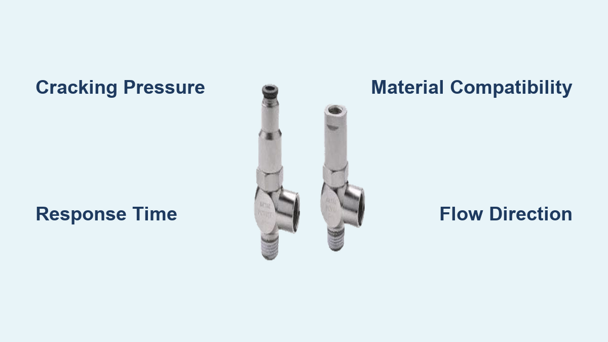
Unlike powered control valves, pneumatic check valves operate passively using only pressure differentials. Yet beneath that simplicity lies critical engineering: cracking pressure, response time, material compatibility, and valve geometry all shape real-world performance. This guide breaks down every major pneumatic check valve type, explains the metrics that matter, and provides actionable selection criteria for applications ranging from compressor protection to vertical load holding and vacuum circuits.
Ball Check Valves: Durable Workhorses for General Air Systems
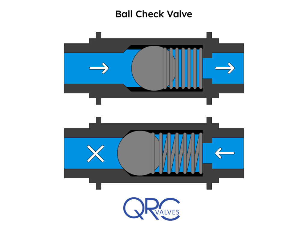
Ball check valves rank among the most widely deployed pneumatic check valve types thanks to their rugged construction and dependable sealing in high-cycle environments.
How Ball Check Valves Operate
A ball check valve uses a spherical element seated against a conical surface. When inlet pressure overcomes the spring force, the ball lifts and moves linearly along a guided bore, allowing forward flow. As soon as pressure drops or reverses, the spring drives the ball back onto the seat, blocking backflow with minimal leakage. The conical geometry keeps the ball aligned, reducing wear and extending service life.
Most pneumatic ball checks include a spring to assist closure, especially in vertical lines where gravity alone may not seat the ball reliably. This spring assist also allows installation in any orientation without performance loss.
Common Applications in Pneumatic Circuits
- Quick-connect couplings that prevent air loss during disconnection
- Bypass lines paired with flow control valves for metered one-way flow
- Compressor discharge lines that stop backflow into the pump head
- Double ball assemblies that provide redundant sealing in critical systems
Strengths and Weaknesses
Advantages
– Rugged design handles high-cycle operation
– Minimal maintenance due to few moving parts
– Spring assist enables any-orientation installation
– Tolerates contamination in filtered air systems
Limitations
– May chatter if oversized or exposed to pulsating flow
– Slight pressure drop from flow redirection around the ball
– Not suitable for dirty air streams without upstream filtration
Poppet Check Valves: Fast, Quiet, and Tight-Sealing
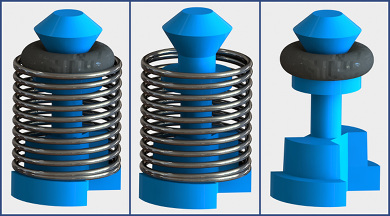
Poppet check valves, sometimes called lift check valves, deliver fast response and reliable shutoff in dynamic pneumatic circuits where speed and stability matter.
Mechanism and Performance Characteristics
A poppet check valve uses a guided plunger or disk that lifts vertically off a sealing seat. A spring holds the poppet closed until inlet pressure reaches the cracking point, typically around 5 psi (0.34 bar) in standard models. Once open, the linear motion creates an unobstructed flow path with minimal pressure drop.
The spring-loaded, guided design closes the poppet rapidly when pressure drops, minimizing air hammer and noise. This makes poppet valves a top choice for high-speed automation requiring quick reversal and stable pressure.
Why Choose Poppet Over Ball
While both designs use spring assistance, poppet valves offer distinct benefits:
– Faster response times from lower moving mass
– More consistent cracking pressure across cycles
– Quieter operation, often marketed as silent check valves
– Better sealing in high-vibration environments
Typical Use Cases
- Flow control bypasses that allow free flow in one direction
- Pilot air protection to prevent backflow into sensitive stages
- Energy recovery circuits maintaining pressure in accumulators
- Vertical cylinder control when paired with pilot valves
Inline Check Valves: Compact Solutions for Tight Spaces
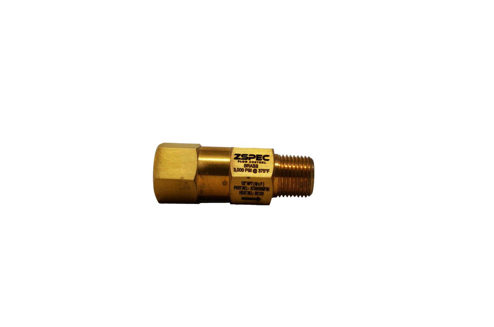
Inline check valves are purpose-built for direct installation into air lines, delivering space-saving integration without sacrificing flow performance.
Design and Installation Flexibility
These valves feature a straight-through body with inlet and outlet ports aligned on the same axis. Manufacturers offer them in brass, aluminum, stainless steel, and plastic, allowing compatibility with general factory air, corrosive media, or sterile environments. Most inline models use a spring-assisted poppet or ball mechanism, enabling installation in any orientation. An arrow on the body marks the correct flow direction, a critical detail for proper function.
Key Selection Factors
- Port size ranging from 1/8″ NPT to 1″ NPT and beyond
- Material choices including lightweight aluminum for manifolds and stainless steel for corrosion resistance
- Cracking pressure around 5 psi standard, with adjustable or high-crack variants available
- Response time as fast as 0.03 seconds in high-performance models like the NKA-20
Where Inline Valves Excel
- Pneumatic actuators needing drift prevention
- Air tool circuits requiring pressure retention during changes
- Multi-circuit systems where branch isolation prevents cross-talk
- Vacuum applications when reversed to allow evacuation while blocking atmospheric backflow
Pilot Operated Check Valves: Positive Locking for Safety-Critical Loads

When safety and precision are non-negotiable, pilot operated check valves provide positive locking in both directions until a command signal releases them.
How They Differ From Standard Check Valves
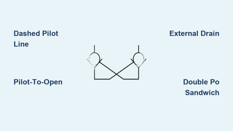
Unlike passive designs, pilot operated check valves require an external pilot pressure signal, usually compressed air, to allow forward flow. Without that signal, the valve remains sealed even under high reverse pressure. Once the pilot signal arrives, the internal mechanism shifts, unlocking the valve for free flow. When the signal stops, the valve relocks instantly, trapping pressure on the load side.
Critical Safety Functions
This locking behavior makes them indispensable in:
– Vertical lifting cylinders where uncontrolled descent must be prevented
– Clamping circuits that must hold workpieces during power loss
– Hose break protection systems that stop sudden pressure loss
Engineers often pair pilot operated check valves with 4-way directional valves to create fail-safe motion control circuits.
Installation Best Practices
- Connect the pilot port to the same line pressurizing the cylinder’s opposing side
- Supply filtered, dry air to prevent pilot passage clogging
- Maintain adequate pilot pressure, typically 60 to 80 percent of system pressure, for reliable unlocking
Reed and Diaphragm Valves: Low-Crack, High-Speed Specialists
For applications demanding minimal cracking pressure and rapid cycling, reed and diaphragm check valves deliver specialized performance.
Reed Valves: Ultra-Fast Response
Constructed from a thin, flexible metal or polymer sheet, reed valves seal against an orifice plate. Their extremely low mass enables:
– Cracking pressures as low as 0.1 psi
– Response times under 0.01 seconds
– Excellent performance in pulsating flows
Common applications include air compressor intake and exhaust valves, two-stroke engine pneumatic components, and low-pressure logic circuits. However, limited flow capacity and fatigue in high-cycle use can restrict their service life.
Diaphragm Check Valves: Clean and Quiet Operation
These valves use a flexible rubber or elastomeric diaphragm that flexes open under forward pressure and seals shut on reversal.
Key features include:
– No metal-to-metal contact, reducing wear
– Resistance to clogging in dusty or humid air
– Silent operation suitable for noise-sensitive environments
– Common use in respirators and medical devices as exhalation valves
Diaphragm valves perform best in low to medium pressure systems where hygiene and quiet operation take priority.
Duckbill and Swing Valves: Niche Pneumatic Applications
While less common in standard pneumatic circuits, duckbill and swing check valves serve specific roles where their unique designs excel.
Duckbill Valves: Self-Cleaning Venting
Made from flexible elastomer shaped like a duck’s beak, these valves open under internal pressure and collapse under back pressure or ambient conditions.
Pneumatic uses include:
– One-way exhaust vents where debris ingestion must be avoided
– Inflatable systems such as mattresses and life rafts that trap air after inflation
– Self-draining lines that prevent moisture buildup
With no springs or moving parts, duckbill valves offer high reliability but are limited to low-pressure differential applications.
Swing Check Valves: Rare in Pneumatic Systems
Typically deployed in large-diameter liquid pipelines, swing check valves use a hinged disc that swings open with flow and closes under reverse pressure.
Why they remain uncommon in air systems:
– Slow closure due to low air density
– Prone to slamming and water hammer
– Require horizontal installation for gravity return
Modified dual-disc wafer types with spring assistance may appear in large HVAC or industrial gas systems where minimizing pressure drop is critical.
Choosing the Right Pneumatic Check Valve Type
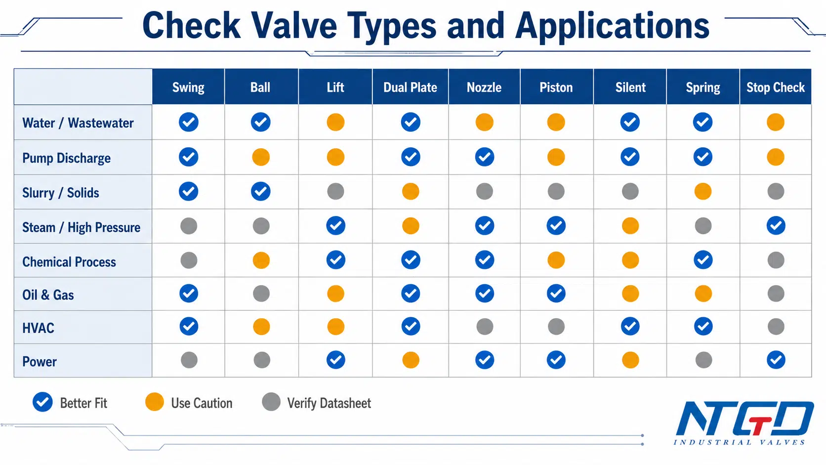
Selecting the correct valve depends on system requirements, operating environment, and performance demands.
Match Cracking Pressure to Application Demands
- Low-pressure systems (1 to 30 psi) need valves with 0.3 to 1 psi cracking pressure
- General automation (80 to 120 psi) typically uses standard 5 psi valves
- Vertical loads or column holding may require higher cracking pressure around 7.5 psi
- Vacuum systems demand valves rated for 10″ Hg (700 mbar) cracking
Prioritize Response Time for Dynamic Circuits
High-speed automation demands fast valves:
– Standard poppet and ball designs: 0.05 to 0.1 seconds
– High-speed models like NKA-20 and NKA-25: 0.03 seconds
– Reed valves: under 0.01 seconds
Always verify response time in manufacturer specifications for critical timing applications.
Consider Material and Environmental Compatibility
| Material | Best For | Avoid In |
|---|---|---|
| Brass | General air lines, moderate temperatures | Highly corrosive or marine environments |
| Aluminum | Lightweight manifolds, automation | Wet, salty, or chemically aggressive air |
| Stainless Steel | Food, pharma, marine, high corrosion | Cost-sensitive, non-critical uses |
| Plastic (PP, PVDF) | Cleanrooms, chemical fumes | High pressure or temperature |
Seal materials including NBR, Viton, and EPDM must also match air quality and any lubricants present in the system.
Size Correctly to Prevent Chattering
An oversized valve won’t stay fully open at low flow, causing the disc or ball to rattle and wear prematurely. An undersized valve creates excessive pressure drop.
Rule of thumb: Size the valve so minimum operating flow keeps the closing element fully lifted throughout the duty cycle.
Installation and Maintenance Best Practices
Even the highest quality valve fails if installed incorrectly or neglected during service.
Install in Correct Flow Direction
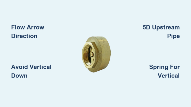
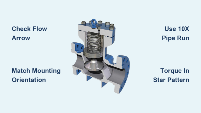
Always align the arrow on the valve body with the intended flow direction. Reversed installation blocks all flow and can damage the system.
Avoid Turbulent Inlet Conditions
Install check valves at least 5 to 10 pipe diameters downstream from elbows, tees, or pumps to prevent turbulence-induced vibration and chattering.
Use Upstream Filtration
Contaminants cause stuck-open valves from debris under the seat, stuck-closed valves from corrosion or clogging, and premature wear. Installing a 5-micron filter upstream is essential in dirty or humid environments.
Troubleshoot Common Failures
| Symptom | Likely Cause | Solution |
|---|---|---|
| Backflow | Worn seat, debris, stuck poppet | Disassemble, clean, replace seals |
| No flow | Valve installed backward, stuck closed | Verify direction, inspect for blockage |
| Chattering | Oversized valve, low flow | Resize, add flow stabilizer |
| Leaking | Damaged seal, cracked body | Replace valve or cartridge |
| Slow response | Weak spring, clogged pilot line | Clean, replace spring or valve |
Frequently Asked Questions About Pneumatic Check Valve Types
What is the most common pneumatic check valve type?
Ball and poppet check valves are the most widely used pneumatic check valve types. Ball designs offer rugged durability for general applications, while poppet designs provide faster response and tighter sealing for dynamic circuits.
How do I choose the right cracking pressure for my system?
Match cracking pressure to your system’s operating range. Low-pressure systems below 30 psi need valves with 0.3 to 1 psi cracking pressure. Standard automation at 80 to 120 psi typically uses 5 psi valves. Vertical load holding may require 7.5 psi or higher to prevent drift.
Can pneumatic check valves work in vacuum applications?
Yes, many pneumatic check valve types operate in vacuum when properly configured. In vacuum mode, the port that normally connects to pressure supply instead connects to the vacuum source, while the application port connects to the system being evacuated. Vacuum cracking pressure is typically rated at 10″ Hg (700 mbar or 532 Torr).
What causes check valve chattering and how do I prevent it?
Chattering occurs when an oversized valve cannot stay fully open at minimum flow, causing rapid cycling of the closing element. Prevent it by correctly sizing the valve so minimum operating flow keeps the ball or poppet fully lifted throughout operation.
Are pilot operated check valves necessary for load holding?
Yes, pilot operated check valves are essential for safety-critical load holding applications such as vertical cylinders and clamping circuits. Standard check valves cannot guarantee positive locking under high reverse pressure, but pilot operated types remain sealed until a deliberate pilot signal releases them.
How often should pneumatic check valves be inspected?
Inspect pneumatic check valves during routine system maintenance, typically every 6 to 12 months depending on cycle rate and air quality. Look for leakage, unusual noise, pressure drops, and visible wear on seals or seats.
Key Takeaways for Selecting Pneumatic Check Valve Types
Pneumatic check valve types are not interchangeable. Ball, poppet, inline, pilot operated, reed, and diaphragm designs each serve distinct roles based on cracking pressure, speed, sealing capability, and environmental demands. Choosing the right one ensures system efficiency, safety, and longevity across applications from receiver tank pressure maintenance to vertical load holding and vacuum circuits.
Before installation, always verify specifications like cracking pressure (commonly 5 psi or 7.5 psi), response time (as fast as 0.03 seconds in high-performance models), and material compatibility with your air quality and operating environment. Match the valve type to your application’s demands, install it with proper filtration and adequate straight pipe runs, and follow a regular inspection schedule. With correct selection and maintenance, pneumatic check valves deliver years of silent, reliable service, keeping compressed air flowing in exactly the right direction.