You are reviewing a piping diagram and spot a small triangle inside a pipe line. What does it mean? That simple shape is the check valve symbol, a critical marker that indicates one-way flow in engineering drawings. Whether you are reading a P&ID, hydraulic schematic, or pneumatic diagram, recognizing and correctly interpreting this symbol prevents costly mistakes like backflow, equipment damage, or system failure. The check valve symbol does not just represent a component; it signals a safeguard that allows fluid to move forward but never backward.
This guide breaks down everything you need to know about the check valve symbol: how it varies by industry, how to read flow direction, what additional marks like springs or pilot lines mean, and how to avoid common installation errors. You will learn to distinguish it from similar symbols, understand performance implications like cracking pressure, and select the right physical valve based on schematic clues, all grounded in standards like ISO 10628-2 and ISO 1219-1.
Check Valve Symbol Basics and Flow Direction Logic
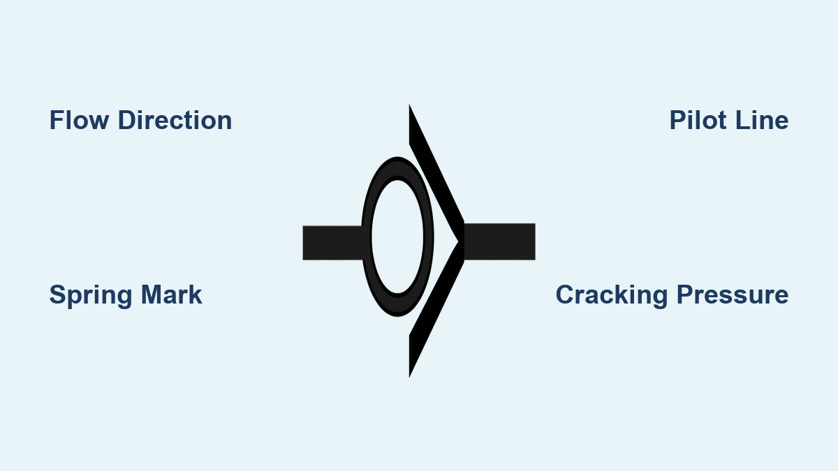
The check valve symbol universally represents a device that allows flow in one direction and blocks reverse flow. While the exact design differs across disciplines, the core idea remains: flow passes when moving with the symbol’s orientation, and it stops when moving against it.
Unlike manual valves such as gate or globe valves, check valves operate automatically based on pressure differential. No handles, actuators, or controls are involved. Their presence on a diagram means backflow prevention is required at that point, commonly on pump discharges, compressor outlets, or branch lines where reverse flow could cause contamination or mechanical damage.
Reading Flow Direction Correctly
To interpret the symbol correctly, follow these guidelines:
- Follow the triangle or flap; in most standards, a triangular or hinged shape points in the allowed flow direction.
- Look for arrows; some diagrams include explicit arrows on the line. If absent, deduce flow from system context, such as from pump discharge to storage tank.
- Identify upstream versus downstream; the side where pressure opens the valve is upstream. Reverse flow pushes the internal element (ball, disc, or flap) into its seat, sealing the line.
Misreading the direction leads to zero flow if installed backward in a non-self-priming system or uncontrolled backflow, risking pump damage or contamination.
P&ID Check Valve Symbol Representation
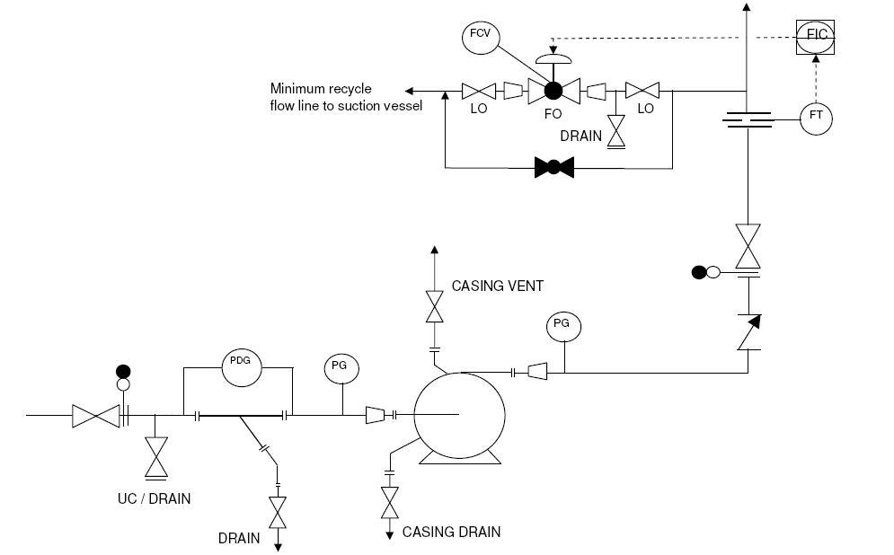
In Process and Instrumentation Diagrams (P&IDs), the check valve symbol follows ISO 10628-2 or company-specific standards. It is often minimal, showing a single line with a triangle or angled flap indicating flow direction.
Standard P&ID Visual Elements
- Visual: A diagonal line or triangle placed across the pipe, pointing with the flow.
- Example: On a pump discharge line, the symbol ensures fluid does not return to the pump when it stops, preventing reverse rotation.
- Limitation: The symbol alone does not specify valve type (swing, lift, ball) or material. Engineers must cross-reference with line lists, valve tags, and specs.
Common Placement in P&IDs
| Location | Purpose |
|---|---|
| Pump discharge | Prevent reverse flow damaging impeller |
| Boiler feed lines | Stop steam or water backflow |
| Branch takeoffs | Isolate sections during shutdown |
| Compressor outlets | Avoid gas return into low-pressure zones |
Always verify orientation relative to connected equipment. A misplaced symbol can imply incorrect installation in the field.
Hydraulic System Check Valve Symbols
Hydraulic schematics follow ISO 1219-1, where check valve symbols are more detailed and often include internal mechanisms like springs or pilot lines.
Basic Hydraulic Check Valve Features
- Symbol: A circle (valve body) with a ball or poppet pressed against a seat. A triangle or arrow shows forward flow.
- Spring mark: A zigzag line indicates a spring-loaded check valve, requiring a minimum cracking pressure to open.
- Function: Used in actuator circuits to lock cylinders in position when the pump is off.
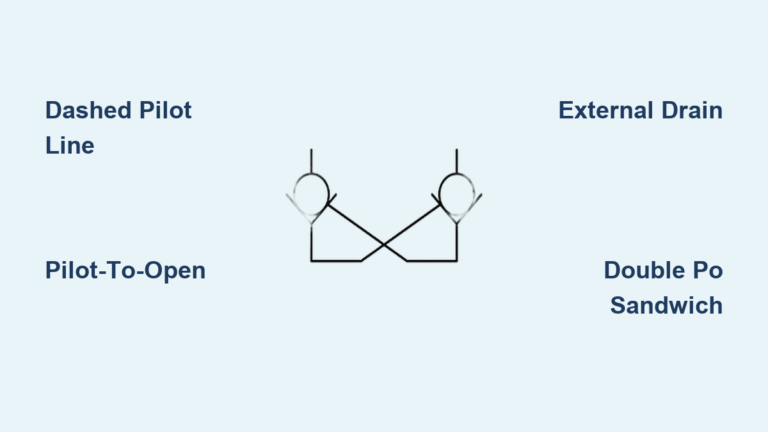
Pilot-Operated Check Valve (PO Check)
- Symbol: Includes a dashed pilot line entering the side of the valve.
- Operation: Normally blocks reverse flow, but when pilot pressure is applied, it lifts the ball, allowing reverse flow.
- Application: Load holding in forklifts, presses, and excavators.
Double PO Check Configuration
- Symbol: Two PO check valves shown side-by-side or in a sandwich block (CETOP standard).
- Purpose: Locks double-acting cylinders in both directions.
- How it works: When the directional valve centers, both checks seal, trapping fluid and preventing drift.
Pneumatic Non-Return Valve Symbol Differences
Pneumatic diagrams use symbols nearly identical to hydraulic ones, but context determines function.
Key Differences from Hydraulic Symbols
- Medium: Air or gas instead of oil.
- Cracking pressure: Typically lower due to compressibility of air.
- Applications: Prevent reverse air flow in control circuits, lock actuators in position, and protect solenoid valves from back-pressure.
Locking Non-Return Valves
- Special type: Can block flow in both directions when triggered.
- Symbol: May include a locking mechanism or dual pilot lines.
- Use case: Safety isolation in hazardous environments such as chemical transfer.
Never assume pneumatic symbols behave exactly like hydraulic ones. Always check the circuit legend.
Check Valve vs. Relief Valve Symbol Distinctions
Confusing these two is a common error with serious consequences.
Check Valve Symbol Characteristics
- Location: In-line with main flow path.
- Function: Controls flow direction.
- Visual: Triangle, ball, or flap; may include spring (zigzag).
- Example: Stops water from flowing back into a well after the pump turns off.
Relief Valve Symbol Characteristics
- Location: Connects main line to tank or reservoir.
- Function: Limits system pressure.
- Visual: Includes a dashed pilot line sensing pressure and an outlet to tank.
- Example: Opens when pressure exceeds set limit, dumping fluid to tank.
A relief valve diverts excess pressure while a check valve enforces one-way flow. Mixing them up can lead to uncontrolled pressure buildup or unintended backflow.
Check Valve vs. Ball Valve Symbol Comparison
Despite similar names, these valves serve entirely different purposes.
Check Valve (One-Way Flow)
- Symbol: Triangle or ball against seat.
- Operation: Automatic.
- Purpose: Prevent backflow.
Ball Valve (Manual On/Off)
- Symbol: Circle with a straight line through it (bore), often with a handle.
- Operation: Manual or actuated quarter-turn.
- Purpose: Start or stop flow in either direction.
Remember that “ball check” refers to the internal mechanism while “ball valve” refers to a manually operated shutoff. The symbols are distinct and must not be interchanged.
Advanced Hydraulic Check Valve Configurations
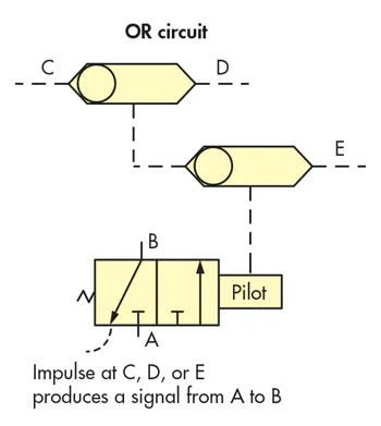
Beyond basic check valves, hydraulic systems use specialized configurations for precise control.
Shuttle Valve (OR Logic)
- Symbol: Two inlets converge to one outlet, with a ball or shuttle inside.
- Function: Delivers the higher of two input pressures to the output.
- Applications: Emergency steering (main plus backup pump), brake systems, and load-sensing circuits.
Box Layout (Four-Check Circuit)
- Symbol: Four check valves arranged around a central flow control.
- Function: Enables bidirectional speed control using a single flow regulator.
- How it works: No matter the main flow direction, fluid always passes through the flow control in the same way.
- Benefit: Consistent extension and retraction speed in hydraulic cylinders.
This configuration eliminates the need for two separate flow controls and ensures balanced performance.
Reading Cracking Pressure from Symbols
While most symbols do not list numerical values, spring markings indicate cracking pressure requirements.
Spring-Loaded Check Valve Symbol Clues
- Zigzag line: Represents the spring.
- Implication: Valve requires minimum upstream pressure to open.
- Design consideration: Too high and the system may not generate enough head to open the valve. Too low and it may allow unintended drainage in vertical lines.
In hydraulic schematics, engineers often annotate the cracking pressure (such as “5 psi”) near the symbol for clarity.
Installation Orientation Clues from Symbols
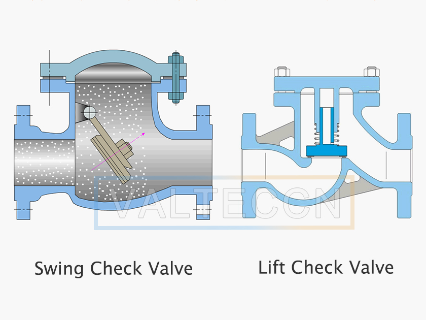
The symbol rarely shows installation limits, but the valve type implied by the symbol does.
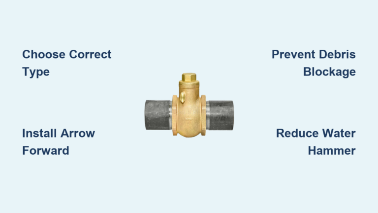
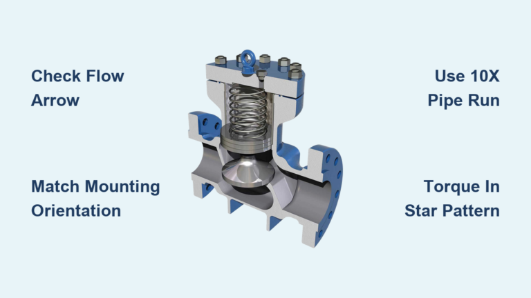
Swing Check Valves
- Symbol: Often shown as a hinged flap.
- Installation: Best in horizontal lines.
- Risk: In vertical downward flow, gravity may prevent closure.
Lift Check Valves
- Symbol: Vertical disc moving along a guide.
- Installation: Requires vertical line with upward flow.
- Why: Gravity helps close the disc.
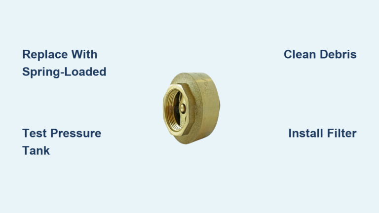
In-Line (Spring-Loaded) Check Valves
- Symbol: Includes spring (zigzag).
- Installation: Can be mounted horizontally or vertically.
- Advantage: Spring provides closing force regardless of orientation.
Always verify orientation limits in specs, even if the symbol looks generic.
Common Mistakes When Interpreting Check Valve Symbols
Misinterpreting the check valve symbol leads to real-world failures.
1. Installing Backward
- Cause: Misreading flow direction.
- Result: No flow or uncontrolled backflow.
- Fix: Double-check arrow direction and equipment layout.
2. Ignoring Cracking Pressure
- Cause: Selecting a spring-loaded valve for a low-head system.
- Result: Valve never opens; pump runs dry or overheats.
- Fix: Match cracking pressure to available system head.
3. Confusing Symbols
- Cause: Mistaking relief valve for check valve.
- Result: Missing backflow protection or incorrect pressure relief.
- Fix: Use legend and context; tank return equals relief, inline equals check.
4. Overlooking Water Hammer
- Cause: Using a swing check in a high-velocity system.
- Result: Disc slams shut, creating pressure spikes.
- Fix: Use non-slam or silent check valves in critical lines.
5. Wrong Orientation
- Cause: Installing a lift check upside down.
- Result: Valve will not close; system drains.
- Fix: Follow manufacturer orientation markings.
RFQ Checklist: From Symbol to Specification

A symbol is not a purchase order. To order the right valve, gather these details:
| Parameter | What to Specify |
|---|---|
| Size | DN or NPS, pipe schedule |
| Pressure/Temperature | ANSI/PN class, max working P/T |
| Medium | Water, oil, steam, chemical (for material selection) |
| Body Material | Brass, stainless steel, PVC, etc. |
| Seat Material | NBR, EPDM, PTFE, metal |
| Connection Type | Threaded, flanged, welded, wafer |
| Valve Type | Swing, lift, ball, spring-loaded |
| Installation Orientation | Horizontal, vertical up/down |
| Cracking Pressure | Required opening pressure |
| Special Needs | Fire-safe, low leakage, non-slam |
This data turns a symbolic triangle into a real, functional component.
Applications of Check Valve Symbols Across Industries
The check valve symbol appears in nearly every fluid system.
Pump Protection Applications
- Foot valves: Installed on suction lines with strainers to maintain prime.
- Discharge checks: Prevent reverse rotation when pump stops.
- Metering pumps: Use tiny ball checks for precise dosing.
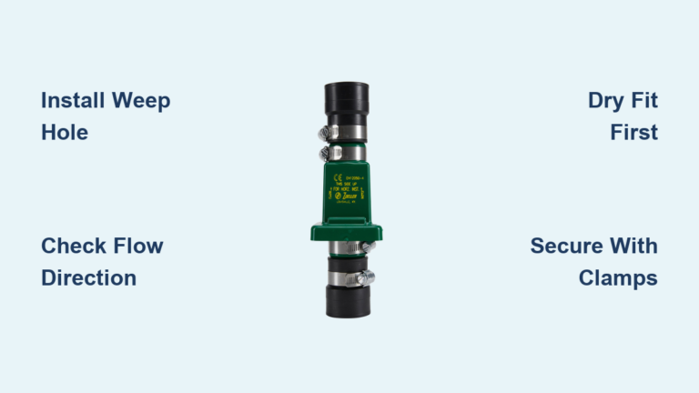
Backflow Prevention (Domestic)
- Required by code when connecting to non-potable systems including lawn irrigation, dishwashers, and industrial process water.
- Prevents contaminated water from entering municipal supply.
Hydronic Heating Systems
- Flow checks (gravity brakes): Stop thermosiphoning in solar thermal or multi-zone systems.
- Feature: Manual override screw to open for air purging.
Aerospace and Nuclear Applications
- High-reliability check valves in aircraft hydraulics, spacecraft propulsion (RCS/ACS), and nuclear feedwater and sampling lines.
- Must withstand vibration, radiation, and extreme temperatures.
Medical and Scientific Applications
- Duckbill valves: No moving parts; used in drainage and infusion devices.
- Reed valves: High-cycle applications like compressors and two-stroke engines.
- Tesla Valve (1920): No moving parts; uses fluid dynamics to resist reverse flow.
Frequently Asked Questions About Check Valve Symbols
What does a triangle in a pipe symbol mean?
A triangle inside a pipe line typically represents a check valve symbol. The triangle points in the direction of permitted flow, indicating that fluid can move forward but cannot reverse. This is one of the most common representations in P&IDs and process diagrams.
How do you identify a check valve symbol on a hydraulic schematic?
On hydraulic schematics following ISO 1219-1, a check valve symbol appears as a circle with a ball or poppet pressed against a seat. A zigzag line indicates a spring-loaded variant, while a dashed line shows a pilot-operated check valve. The triangle or arrow shows the permitted flow direction.
What is the difference between a check valve symbol and a relief valve symbol?
A check valve symbol sits in-line with the main flow path to enforce one-way flow. A relief valve symbol connects the main line to a tank or reservoir with a dashed pilot line sensing pressure. Relief valves limit system pressure, while check valves control flow direction.
Why does a check valve symbol sometimes include a zigzag line?
The zigzag line in a check valve symbol represents a spring. This indicates a spring-loaded check valve that requires a minimum cracking pressure to open. The spring also ensures the valve closes quickly when flow stops, preventing backflow and reducing water hammer risk.
Can a check valve symbol indicate installation orientation?
The symbol itself rarely shows orientation limits, but the valve type implied by the symbol does. Swing checks are best installed horizontally, lift checks require vertical upward flow, and spring-loaded in-line checks can be mounted in any orientation. Always verify orientation in the manufacturer specifications.
What is the difference between a ball check valve symbol and a ball valve symbol?
A ball check valve symbol shows a ball against a seat to prevent reverse flow automatically. A ball valve symbol shows a circle with a straight line through it representing the bore, often with a handle indicator for manual quarter-turn operation. They serve entirely different functions despite sharing the word “ball.”
Key Takeaways for Mastering the Check Valve Symbol
The check valve symbol is a small but powerful icon in engineering drawings. It tells you where backflow protection is needed but not how to implement it. Success depends on understanding flow direction, valve type, cracking pressure, orientation, and system context.
Always verify flow with system logic, cross-reference symbols with specifications, choose the right physical valve for the service, and install in the correct orientation. By mastering the meaning behind the symbol, you ensure safety, efficiency, and reliability in every system you design, maintain, or operate.