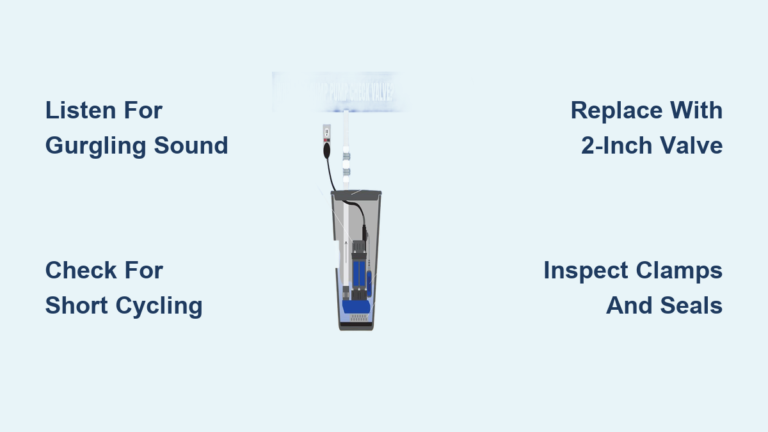
Installing a swing check valve in a vertical pipe is not as simple as dropping it into the line. Get the orientation wrong, and you risk violent water hammer, backflow contamination, or a ruptured pipeline within hours of startup. The swing check valve depends on gravity to close its hinged disc when flow stops, which means the physics of your installation matter far more than the physical fit of the valve.
This guide walks you through every critical rule for swing check valve vertical installation. You will learn which flow directions are safe, how to prevent destructive pressure surges, what to inspect before mounting, and when to choose a different valve type entirely. Follow these field-proven practices and your installation will perform reliably for years.
Why Flow Direction Dictates Swing Check Valve Vertical Installation Success

Upward Flow Is the Only Safe Option
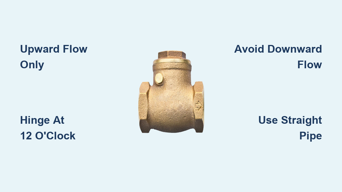
Mount a swing check valve in a vertical line only when fluid travels upward. The valve body sits horizontally across the vertical pipe, with the hinge pin locked at the 12 o’clock position. This setup lets the disc swing open against gravity during forward flow and drop shut when flow stops or reverses. The flow arrow cast into the valve body must point straight up. Any deviation from this rule risks improper closure and costly system damage.
Why Downward Flow Causes Catastrophic Failure
Never install a swing check valve in a vertical pipe carrying downward flow. Gravity pulls the disc open instead of allowing it to close. When forward flow halts, the disc may stay partially or fully open, letting contaminated fluid backflow into your clean supply. Worse, when system pressure eventually forces the disc shut, gravity accelerates it into the seat with tremendous force. This creates severe water hammer that can rupture pipes, crack valve bodies, or destroy connected equipment.
The Flow Arrow Alignment Check
Before mounting, locate the flow arrow on the valve body. It must align exactly with the intended direction of flow, which means straight up for vertical installations. Installing the valve backward blocks flow entirely or demands dangerous pressure levels to force the disc open. A reversed valve is a hidden hazard that often goes unnoticed until something fails. Always double-check orientation even when the piping layout seems to dictate direction.
Preventing Water Hammer in Vertical Swing Check Valve Installations
How Slam Closure Creates Pressure Surges
Water hammer happens when moving fluid stops suddenly, generating a high-pressure shock wave. In swing check valves, this occurs during slam closure, when the disc shuts rapidly without controlled damping. In a misaligned vertical setup, gravity accelerates the disc into the seat with extreme force. The trapped fluid column rebounds violently, creating pressure spikes thousands of times higher than normal operating levels. These surges can burst pipes, loosen joints, and destroy downstream equipment in a fraction of a second.
Why Vertical Lines Amplify Water Hammer Risk
Vertical systems magnify water hammer danger because falling fluid adds momentum to the closing event. If a swing check is installed with downward flow, the entire vertical fluid column crashes onto the closing disc. Even in correct upward-flow setups, undersized valves or excessive flow velocities can trigger fast closure. Treat every vertical installation as a high-risk surge scenario unless you have installed proper mitigation equipment.
Surge Suppression Devices That Protect Your System
Protect your system by adding surge dampers, hydraulic accumulators, or snubbers downstream of vertical swing check valves. These devices absorb kinetic energy from sudden flow stops and reduce peak pressure. In critical systems such as fire protection lines or high-pressure pump stations, use slow-closing or non-slam check valves instead of standard swing types. For existing installations prone to hammer, retrofitting a pressure relief valve or expansion tank can prevent catastrophic failures.
Pre-Inspection Steps Before Swing Check Valve Vertical Installation
Verify Valve Specifications Match Your Pipeline
Confirm the valve matches your pipeline in size, pressure rating, and connection type. Common connection styles include flanged, threaded, and socket weld. Ensure material compatibility by selecting PVC for corrosive fluids or stainless steel for high-temperature or sterile systems. Check manufacturer specifications for maximum allowable pressure and temperature ratings. Using an undersized or incompatible valve invites leaks, warping, or catastrophic failure under operational loads.
Inspect Internal Components for Damage and Debris
Remove end caps and visually examine the interior cavity. Look for shipping debris, plastic fragments, or packing material that could jam the disc during operation. Inspect the sealing surfaces, including both the disc edge and the seat, for scratches, burrs, or dents. Even minor imperfections cause leakage when the valve closes. Test disc movement by gently pushing it open; it should swing freely without binding. If the hinge pin feels loose or shows corrosion, replace the valve before installation.
Confirm the Hinge Pin Position Before Mounting
Ensure the hinge pin is intact and positioned at the top of the valve body in the 12 o’clock location. This placement is critical for gravity-assisted closure. In vertical installations, rotate the entire valve so the pin stays at the highest point regardless of pipe direction. A pin located at 3, 6, or 9 o’clock prevents proper disc drop and increases the risk of flutter or slam events during operation.
Step-by-Step Mounting Procedure for Vertical Installations

Align the Valve in the Vertical Pipe
For vertical upward flow installations, follow this sequence:
- Cut the pipe and prepare clean, square ends.
- Position the swing check valve so the body sits horizontally and the flow arrow points up.
- Rotate the valve until the hinge pin reaches the 12 o’clock position.
- Support the valve independently so pipe weight does not stress the connections.
Use alignment clamps or temporary brackets to hold the valve in position during welding or threading. Misalignment causes binding, leaks, and premature wear on the hinge mechanism.
Secure Connections Using Proper Techniques
Choose the right method based on your connection type:
- Threaded Valves: Hand-tighten first, then use wrenches to secure. Avoid over-tightening, which cracks cast bodies or distorts threads.
- Flanged Valves: Align flanges squarely. Tighten bolts in a star pattern to distribute pressure evenly and prevent gasket blowout.
- Socket Weld or CPVC: Use correct solvent cement or welding technique. Allow full cure time before pressurizing the system.
Always support both sides of the connection to avoid stress on the valve body.
Provide Adequate Clearance Around the Disc
Leave 1 to 2 pipe diameters of open space around the valve, especially on the disc side. For a 4-inch valve, this means 4 to 8 inches of clearance. Adequate space ensures the disc swings fully open without hitting pipe supports, insulation, or adjacent equipment. Restricted movement increases pressure drop, causes turbulence, and accelerates wear on internal components.
Establishing Laminar Flow for Valve Stability
Install Upstream Straight Pipe Sections
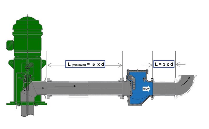
Do not place a swing check valve immediately after an elbow, tee, or pump discharge. Turbulent, swirling flow causes the disc to flutter, stick, or close unevenly. This leads to premature wear, leakage, and operational noise. Install 5 to 10 pipe diameters of straight pipe upstream of the valve inlet. For a 6-inch line, that translates to 30 to 60 inches of straight run to stabilize the flow profile before it reaches the valve.
Reduce Turbulence from Pump Discharge
If installing downstream of a pump, extend the straight pipe section to 10 diameters or install a flow straightener. Pump discharge creates highly turbulent flow that destabilizes the disc mechanism. In vertical risers fed by horizontal pumps, use a 90-degree elbow with vanes or a diffuser to reduce swirl before the check valve. These modifications prevent oscillation and extend valve service life.
Use Flow Conditioners in Tight Spaces
In tight spaces where straight pipe runs are impossible, install a flow conditioner or diffuser plate upstream. These devices break up vortices and equalize velocity across the pipe diameter. While not a complete substitute for straight pipe, flow conditioners reduce disc oscillation and improve valve longevity in constrained installations.
Post-Installation Testing Protocols
Conduct Leak and Pressure Tests
After installation, follow these steps to verify system integrity:
- Isolate the section and slowly pressurize with water or air.
- Check all joints, flanges, and the valve body for leaks.
- Hold pressure for 10 to 15 minutes. Any drop indicates a seal failure.
For high-pressure systems, follow ASME B31.1 or B31.3 hydrotest procedures. Never exceed the valve’s rated pressure during testing.
Verify Disc Operation Under Flow
If using clear PVC swing checks, visually confirm the disc behavior:
- The disc swings fully open during flow.
- It drops shut immediately when flow stops.
- No debris is trapped in the seat area.
For metal valves, listen for a clean thud when flow stops, which indicates positive closure. A soft click or no sound may signal slow or incomplete sealing that requires adjustment.
Simulate Flow Stoppage to Check Closure
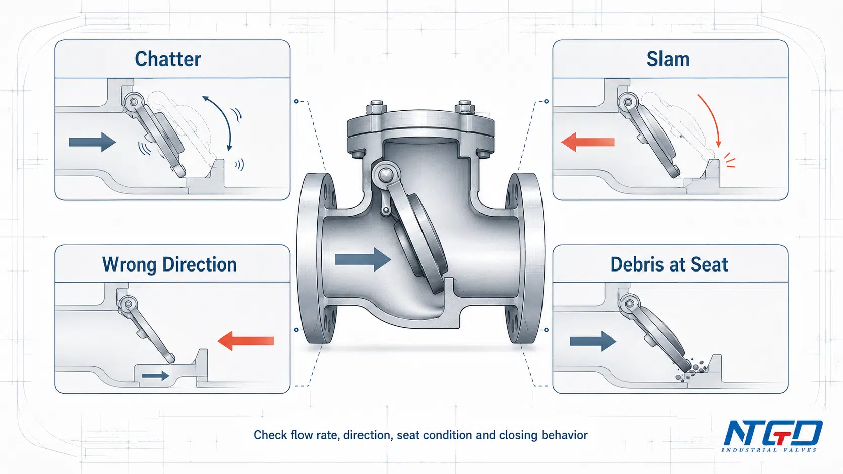
Shut off the pump or upstream valve abruptly to test closure behavior. The disc should close without prolonged flutter or vibration. If you hear chattering or a loud slam, the system may be prone to water hammer. Consider adding damping equipment or switching to a non-slam valve design to protect your infrastructure.
Routine Maintenance for Long-Term Reliability
Schedule Regular Visual Inspections
Inspect valves monthly in critical systems such as fire pumps and process lines. Look for external leaks at joints or the bonnet, corrosion or pitting on the body and bolts, loose supports or misalignment, and unusual vibration during operation. Early detection prevents unplanned downtime and expensive repairs.
Clean and Exercise the Disc Periodically
In systems with infrequent use, manually exercise the disc every 3 to 6 months. Turn off flow, relieve pressure, and gently open the cover if accessible. Move the disc through its full swing range to prevent sticking. Clean any sediment or mineral buildup from the seat surface. For permanently sealed valves, cycle the system manually to ensure disc movement remains unrestricted.
Monitor for Flutter and Unusual Noise
Persistent chattering, buzzing, or vibrating during low-flow periods indicates disc instability. Common causes include:
- Flow velocity below 2 ft/s
- Oversized valve relative to system demand
- Turbulent inlet flow conditions
If flutter occurs, consider downsizing the valve or replacing it with a lift check or piston check designed for low-flow applications.
Common Failure Causes and Quick Fixes
Diagnosing Leaks When the Valve Is Closed
If the valve passes flow in reverse, check these potential causes:
- Debris on seat: Shut off the system, disassemble the valve, and clean the sealing surfaces thoroughly.
- Damaged disc or seat: Inspect for cracks, warping, or erosion. Replace damaged parts or the entire valve.
- Worn hinge: A loose disc will not seal evenly. Replace the valve if play exceeds manufacturer specifications.
Never grind or file sealing surfaces, as this ruins the precision fit required for reliable closure.
Troubleshooting Valves That Won’t Open
If forward flow is blocked, investigate these issues:
- Disc jammed by debris: Open the valve and remove the obstruction.
- Backward installation: Confirm the flow arrow points in the correct direction.
- Disc stuck on seat: In stagnant systems, mineral deposits can glue the disc shut. Exercise the valve regularly or install a bypass line.
Resolving Disc Flutter and Vibration
Flutter occurs when flow velocity is too low (below 2 ft/s) or inlet flow is turbulent. Effective solutions include:
- Resize the valve to match actual system flow rates.
- Add upstream straight pipe to stabilize inlet conditions.
- Switch to a lift check valve, which performs better at low differential pressure.
Persistent flutter leads to hinge fatigue and eventual valve failure.
Applications Where Swing Check Valves Should Be Avoided
Low-Flow and Gravity-Fed Systems
Avoid swing checks in gravity-fed lines, condensate returns, or HVAC bypass loops where flow is slow. The disc will not lift fully, causing partial blockage and vibration. Use lift check or tilting disc check valves instead, as they require less force to open and close smoothly at low velocities.
High-Cycle Pump Applications
Systems with frequent pump starts, such as booster pumps and irrigation systems, wear out swing check hinges quickly. The repeated impact fatigues the pin and deforms the hinge bore. Choose forged piston check valves or dual-plate wafer checks rated for high cycling. If a swing check is the only option, add a surge suppressor to reduce closure speed and extend service life.
Any Downward Flow Configuration
There is no safe way to install a swing check valve in a vertical pipe with downward flow. The physics work against the design. Use ball check, spring-assisted lift check, or nozzle check valves in these applications, since they rely on spring force or fluid dynamics rather than gravity for proper closure.
Best Practices Checklist for Swing Check Valve Vertical Installation
Review these critical points before completing your installation:
- Hinge Position: Always mount the valve so the hinge pin sits at the top in the 12 o’clock position, whether in horizontal or vertical lines.
- Clearance Rules: Maintain 1 to 2 pipe diameters of clearance around the valve and 5 to 10 pipe diameters of straight pipe upstream.
- System Compatibility: Use swing checks only when flow is upward in vertical pipes, velocity exceeds 2 ft/s, flow is steady rather than pulsating, and cycle frequency is low to moderate.
- Safety Priority: Taking shortcuts like installing with downward flow or skipping straight pipe leads to expensive failures. Water hammer can destroy hundreds of feet of piping in seconds.
Frequently Asked Questions About Swing Check Valve Vertical Installation
Can a swing check valve be installed vertically?
Yes, but only when fluid flow moves upward through the valve. The valve body must remain horizontal with the hinge pin at the 12 o’clock position. Installing with downward flow is strictly prohibited because gravity prevents proper disc closure and creates severe water hammer risk.
What happens if you install a swing check valve backwards?
A backward installation blocks forward flow or forces the disc open under dangerous pressure levels. This can fracture the hinge pin, damage the seat, and cause the valve to fail completely. Always verify the flow arrow points in the correct direction before securing connections.
Why is downward flow dangerous for swing check valves?
Downward flow causes gravity to hold the disc open instead of allowing it to close. When forward flow stops, the disc slams shut under combined gravitational and fluid forces, generating destructive water hammer. This can rupture pipes, crack valve bodies, and destroy connected equipment.
How much straight pipe is needed before a swing check valve?
Install 5 to 10 pipe diameters of straight pipe upstream of the valve inlet. For a 6-inch line, this means 30 to 60 inches of straight run. Adequate straight pipe ensures laminar flow conditions and prevents disc flutter or oscillation.
What is the minimum flow velocity for a swing check valve?
Swing check valves require a minimum flow velocity of 2 ft/s (0.6 m/s) to lift the disc fully. Below this threshold, the disc may not open completely, leading to flutter, vibration, and premature wear. Use lift check or piston check valves for low-velocity applications.
How do you stop water hammer in a vertical swing check installation?
Install surge suppression devices such as dampers, hydraulic accumulators, or snubbers downstream of the valve. These absorb kinetic energy from sudden flow stops and reduce peak pressure. For critical systems, consider switching to slow-closing or non-slam check valves designed to prevent surge events.
Key Takeaways for Successful Swing Check Valve Vertical Installation
Swing check valve vertical installation succeeds when you respect three non-negotiable rules: flow must move upward, the hinge pin must sit at 12 o’clock, and adequate straight pipe must precede the valve. Skip any of these requirements and you invite water hammer, backflow, or catastrophic system failure.
Before your next installation, verify the flow direction, inspect the valve internals